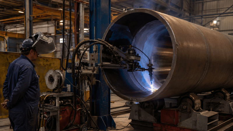
A TIG cladding machine can produce corrosion-resistant overlays with excellent process control—provided the system actually matches the component. Choose equipment from a brochure headline alone, and you may simply automate the wrong process faster.
This guide explains how to compare machine configurations, control dilution, assess productivity, and verify performance before purchase.
What Is a TIG Cladding Machine?
A TIG cladding machine is an automated or mechanized system that deposits a protective alloy layer using gas tungsten arc welding, also known as GTAW.
The system coordinates torch movement, component rotation, filler-wire feeding, shielding gas, bead overlap, and layer sequencing. The goal is not merely to deposit metal. It is to achieve the required overlay thickness, chemistry, fusion, and coverage.
TIG cladding is one form of weld overlay. “Cladding” usually refers to the protective layer, while “weld overlay” describes the deposition method. In most equipment discussions, the terms are used interchangeably.
For a broader explanation of welding terminology, see this technical overview from TWI.
Why Automate TIG Weld Overlay?
Manual TIG can produce excellent welds, but long circumferential overlays and repetitive bores challenge operator consistency. Torch angle, travel speed, wire placement, and arc length may gradually change during production.
An automatic cladding machine maintains programmed motion and welding parameters across repeated beads and layers. This improves bead consistency, overlap control, heat-input stability, and wire positioning.
Automation can also provide recipe storage, alarm histories, parameter monitoring, and weld data logging. These functions help manufacturers document that production followed an approved procedure rather than relying on an operator’s memory.
However, automation does not repair a weak welding procedure. It repeats whatever it is programmed to do—including mistakes. Sample welding and qualification remain essential.
Main TIG Cladding Machine Configurations
The correct configuration begins with component geometry, not the most impressive machine video.
Horizontal Systems
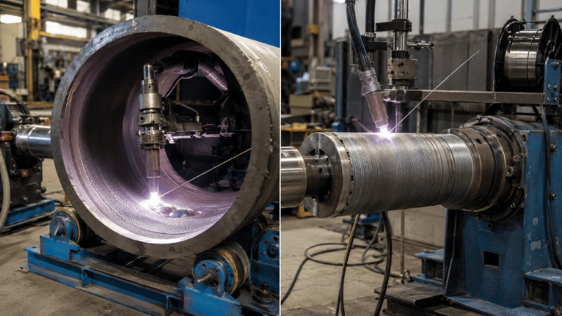
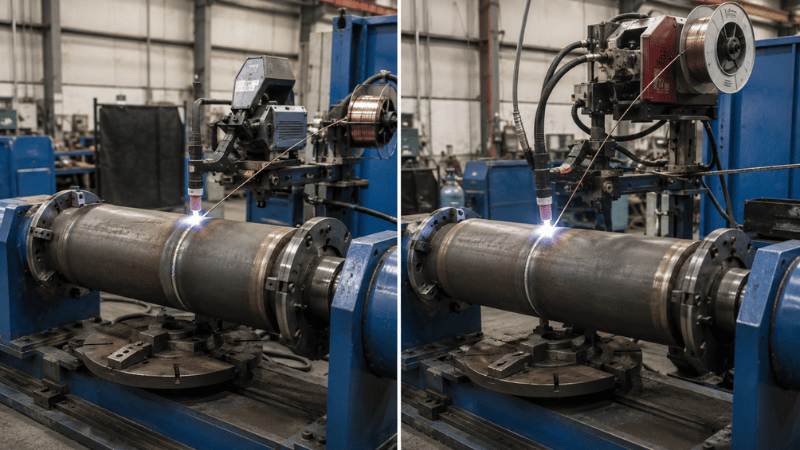
Horizontal systems commonly process pipes, tubes, shafts, cylinders, and pressure-equipment parts. The workpiece may rotate while the torch travels axially, supporting ID, OD, circumferential, or longitudinal overlay.
Performance depends on concentric rotation, stable support, torch reach, and wire placement.
For cylindrical components, the MWHF-HL automatic TIG cladding system shows how rotary motion, programmable controls, and multi-axis positioning can be combined in one platform.
Vertical Systems
Vertical systems are often suitable for valve bodies, flanges, fittings, seats, nozzles, and heavy parts that are difficult to support horizontally.
Buyers should evaluate loading method, molten-pool behavior, fixture stiffness, and practical torch access. A machine may offer enough axis travel on paper but still lack space once the torch, wire guide, gas cup, and fixture occupy the same area.
ID, OD, and Deep-Bore Cladding
OD cladding normally offers easier access and monitoring. ID cladding is more demanding because torch clearance, shielding gas, cooling, wire position, and visibility become restricted.
For deep bores, specify bore diameter, depth, transition geometry, cladding start point, and working clearance. Maximum bore depth means little unless the minimum workable diameter is also defined.
From 9.2% Iron Dilution to 100% First-Pass Qualification
A Shandong subsea equipment plant upgraded deep-bore Inconel 625 cladding on F22 valve bodies with the iKratz MWHF-HL Hot-Wire TIG System.
Excessive Dilution
Higher current melted too much F22 base metal, pushing iron content to 9.2% and scrapping the first 12 valve bodies.
Deep-Bore Instability
A weak 450 mm torch extension vibrated badly, causing arc-length changes, lack of fusion, and burn-through.
💸 Financial Toll
🚀 The iKratz Upgrade
Hot-Wire Preheating
Delivered 2.5 kg/h deposition without raising arc current, holding iron content at 3.8%.
AVC Arc Tracking
Maintained a stable 1.0 mm arc gap inside the 450 mm bore.
Remote Monitoring
Industrial cameras gave operators a clear view of the hidden weld pool.
Cold-Wire vs. Hot-Wire TIG Cladding
Cold-wire TIG feeds filler wire into the weld pool without electrical preheating. It offers straightforward control and is well suited to complex geometries, lower production volumes, and applications where precision matters more than maximum output.
Hot-wire TIG electrically preheats the filler wire before it reaches the weld pool. Because less arc energy is needed to melt the wire, the process can achieve a higher deposition rate.
That advantage is application-dependent. Restricted access, short weld lengths, frequent starts, poor wire positioning, or long handling times can reduce the productivity gain.
A hot-wire surfacing welding system is worth considering for repeated pipe, valve, fitting, or cylindrical overlay using stainless or nickel-based filler metals.
Choose between cold wire and hot wire according to deposition target, alloy, allowable dilution, overlay thickness, geometry, and production volume.
Dilution and Deposited Chemistry
Dilution is the proportion of base metal mixed into the deposited weld metal. Some dilution is required for fusion, but excessive dilution can reduce corrosion or wear resistance by changing the final overlay chemistry.
Current, travel speed, wire-feed rate, torch position, bead overlap, and layer strategy all influence dilution. Increasing current may improve fusion but also melt more substrate.
This is why deposition rate and dilution must be evaluated together. A faster process is not truly productive if it requires an extra layer, more machining, or repeated chemistry corrections.
For a practical explanation of base-metal mixing, see the iKratz guide to welding stainless steel to carbon steel.
Single-layer cladding can reduce cycle time but demands tighter chemistry control. Multi-layer cladding usually reduces base-metal influence in the final surface, although it increases wire use, heat input, and machining allowance.
The final procedure should be verified using representative coupons, macro sections, chemistry measurements, and applicable qualification requirements.
Materials and Applications
Typical applications include pipes, valve bodies, valve seats, fittings, flanges, wellhead components, pump parts, nozzles, heat exchangers, and pressure-equipment components.
Common combinations include carbon steel with stainless overlay, low-alloy steel with nickel alloy, and components overlaid with duplex, super-duplex, cobalt-based, or nickel-based materials.
Material names alone are not enough for machine selection. Buyers must also consider cracking sensitivity, preheat, interpass temperature, heat treatment, machining allowance, and the final service environment.
The Nickel Institute guide to clad steel provides useful background on corrosion-resistant alloy cladding.
Automation Features Worth Evaluating
A capable cladding welding machine may include PLC or CNC control, servo-driven axes, programmable rotation, synchronized wire feeding, torch oscillation, arc-voltage control, and automatic layer sequencing.
Arc-voltage control helps maintain consistent arc length when component runout or surface variation cannot be eliminated. It should not replace accurate fixturing or stable rotation.
Recipe storage is valuable for repeated part families. A complete recipe may include current, travel speed, wire feed, oscillation width, dwell time, step-over, gas timing, and layer sequence.
For traceable production, request weld-parameter recording, alarm logs, batch identification, user-access control, and exportable reports. Camera monitoring may help with ID cladding, but image quality should be tested under actual bore and arc conditions.
How to Choose a TIG Cladding Machine
Begin with the component drawing. Define diameter, length, weight, cladding location, bore depth, orientation, and access restrictions. Add photos when castings, repairs, or older parts differ from ideal CAD geometry.
Next, define the welding requirement: base material, filler alloy, overlay thickness, machining allowance, number of layers, deposited chemistry, preheat, interpass limits, and inspection method.
Then define production needs. Consider annual volume, batch size, product variation, loading time, preheating, changeover frequency, and target cycle time.
For a wider discussion of automation variables, see this guide to choosing an automatic pipe welding machine.
A practical scoring model can assign 25% to component compatibility, 20% to quality capability, 20% to productivity, 15% to automation and traceability, 10% to supplier support, and 10% to lifecycle cost.
This prevents one attractive feature—usually deposition speed—from dominating the entire decision.
Measure Real Cycle Time
Cycle time is not simply deposited weight divided by kilograms per hour. Actual production also includes loading, alignment, preheating, arc starts, interpass waiting, inspection, unloading, and setup corrections.
Ask suppliers to separate arc-on time from total part-to-part cycle time. Otherwise, the quoted number may assume that the component loads itself and never requires inspection.
Trials should use representative components or coupons. The report should record part dimensions, materials, filler wire, parameters, deposited weight, total cycle time, interruptions, thickness, and inspection results.
Factory Acceptance Testing
A factory acceptance test should verify the complete process, not merely prove that every axis moves.
Run the agreed program on a representative part. Check overlay coverage, layer sequence, bead consistency, start-stop areas, alarms, recipe recall, and data recording.
Inspection may include visual examination, dye penetrant testing, macro sections, thickness measurement, chemistry analysis, hardness testing, or corrosion testing.
Acceptance limits should be agreed before testing. “Looks good” is an opinion; a measurable result is engineering.
Welding safety, extraction, electrical protection, and operator access should also be reviewed. OSHA provides an overview of welding, cutting, and brazing safety.

Common Problems
Excessive dilution may require adjustments to current, travel speed, wire input, torch position, overlap, or layer strategy. Lowering current alone may create fusion problems, so every change must be validated.
Inconsistent beads often result from unstable rotation, incorrect torch distance, component runout, wandering wire, or poorly tuned oscillation.
Porosity and fusion problems require checks on cleaning, gas coverage, wire condition, contamination, access, and heat input.
Poor repeatability may come from uncontrolled setup dimensions rather than the welding program. Fixture position, electrode extension, wire angle, and component datum points should therefore be recorded.
Information Needed for a Quotation
A useful quotation request should include component drawings, photos, dimensions, weight, base material, filler alloy, cladding surface, overlay thickness, machining allowance, annual volume, batch size, inspection standard, preferred orientation, and facility constraints.
Also define loading method and whether the system requires preheating, extraction, cooling, cameras, seam tracking, data logging, or integration with existing equipment.
“We need a machine for valves” is not a specification. It is the beginning of one.
FAQs
Is TIG cladding the same as weld overlay?
TIG cladding is a type of weld overlay performed using TIG or GTAW. Weld overlay is the broader category and may also use other welding processes.
Should I choose cold-wire or hot-wire TIG cladding?
The choice depends on geometry, filler alloy, dilution limit, overlay thickness, deposition target, and production volume. Hot wire can improve output, but it is not always the best option for complex parts.
Can one machine handle both ID and OD cladding?
Some customized systems can support both. The actual range depends on bore diameter, depth, torch clearance, fixtures, component weight, and orientation.
Conclusion
The best TIG cladding machine is designed around the actual component, alloy, access conditions, quality requirements, and production target.
Do not select equipment by deposition-rate claims alone. Validate the system through representative sample welding, realistic cycle-time analysis, measurable inspection results, and a clearly defined factory acceptance test.
Build a Cladding System Around Your Component
iKratz develops automated TIG and hot-wire overlay systems based on real component dimensions, materials, cladding locations, inspection requirements, and production goals. This application-focused approach helps reduce tooling errors, access problems, unstable rotation, and unnecessary automation.
Share your drawing, alloy, overlay thickness, dimensions, and target output with our team. Contact us today for a technical recommendation and project quotation.