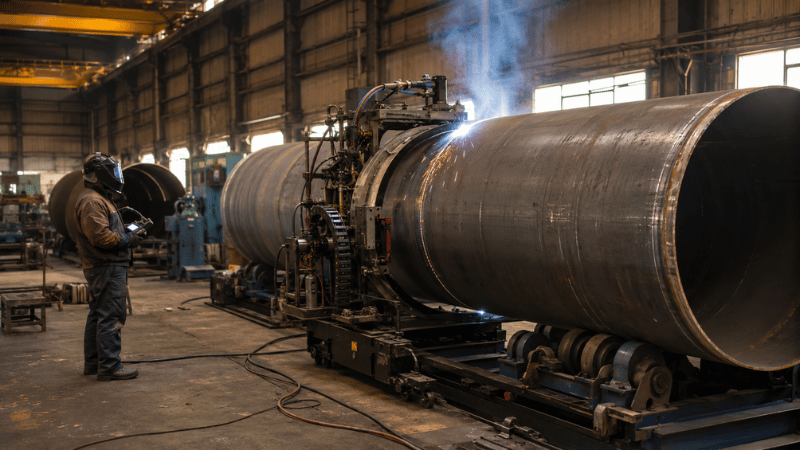
Choosing an automatic pipe welding machine is less like buying a power tool and more like hiring a tireless, extremely precise welder. Pick the wrong system, and it may automate defects at impressive speed.
This guide explains how to match the process, weld head, pipe geometry, quality targets, and ownership cost—then prove the choice through representative test welds.
How Does an Automatic Pipe Welding Machine Work?
An automatic pipe welding machine controls some or all of the variables normally managed by a welder: travel speed, current, voltage, wire feed, oscillation, torch position, and welding sequence.
The term covers several equipment categories. Mechanized systems move the torch while an operator monitors and adjusts the process. Automatic systems follow a programmed cycle with limited intervention. Robotic systems add programmable multi-axis movement.
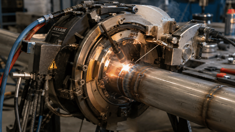
Orbital welding is one branch of pipe welding automation. The weld head or carriage travels around a stationary pipe, maintaining controlled movement through the flat, vertical, and overhead positions. TWI notes that repeatable programs and real-time monitoring can improve both productivity and weld consistency.
A normal cycle includes pipe preparation, alignment, equipment mounting, program selection, root welding, fill and cap passes, inspection, and data recording. The clever controller cannot rescue dirty bevels or heroic root gaps. Automation is capable, but it is not magical.
Main Types of Automatic Pipe Welding Machines
Machine selection begins with the joint—not the brochure photography. Pipe diameter matters, but wall thickness, bevel design, filler requirements, access, and production environment often eliminate unsuitable systems before diameter does.
Orbital Welding System Comparison
Choose the system based on joint type, access, and production needs.
| System Type | Best Suited To | Main Limitation |
|---|---|---|
| Closed orbital weld head | Small, thin-wall, high-purity tubing | Limited clearance, thickness, and filler-wire capability |
| Open orbital weld head | Medium pipe, beveled joints, filler wire, and multi-pass welding | More sensitive to setup and shielding variation |
| Track-mounted system | Large-diameter pipe and field girth welds | Track installation and alignment take time |
| Internal-diameter system | Joints with restricted external access | Requires specialized tooling and engineering |
| Fixed workshop system | Repetitive pipe, flange, vessel, and spool production | Less portable and needs more floor space |
Closed heads provide an enclosed shielding chamber and are commonly selected for autogenous orbital TIG welding. They shine when fit-up is precise and contamination control matters.
Open heads leave the torch accessible, allowing filler wire, torch adjustment, and multi-pass operation. For example, the MWG-230 open orbital welding head is currently specified for pipe diameters from 20 to 230 mm and wall thicknesses up to 8 mm. Those figures are useful screening data, but an application-proven range should still be confirmed through testing.
Track-mounted carriages are generally more suitable when pipe diameter, wall thickness, or field access moves beyond the practical range of a compact orbital head. Fixed workshop systems may instead rotate the workpiece beneath a stationary torch using positioners, rotators, or circumferential welding equipment.
A Budget Welder Caused an $18,100 Repair Crisis
A Xi’an heating contractor used a low-cost orbital welder on DN150 pipe. Ovality, dust, and unstable feeding disrupted the project.
2 mm “Hi-Low” Misalignment
A 2 mm mismatch caused lack of fusion at high points and burn-through at low points. RT qualification fell below 50%.
Dust-Induced Wire Jams
Dust clogged the conduit, while the single-drive feeder caused wire stubbing, arc stops, and downtime.
Dual-Drive Wire Feeding
The dual-drive feeder and Teflon liner stabilized wire feeding and eliminated recurring jams.
Weld-Pool “Bridging” Control
The MWA-200 bridged the 2 mm mismatch, achieving full penetration without burn-through.
The bottom line: the MWG-230 restored weld quality, protected the schedule, and stopped further penalties.
Choose the Welding Process Before the Machine
Buying a machine before selecting the process is a little like choosing a truck before deciding whether you are hauling bricks or birthday cakes. Both are cargo, technically, but the details become important rather quickly.
Orbital GTAW or TIG
Orbital TIG welding offers excellent arc control, clean welds, and stable heat input. It is a strong choice for stainless steel, titanium, nickel alloys, root passes, and applications requiring high-integrity welds.
TIG uses a non-consumable tungsten electrode and can operate autogenously or with filler wire. Its main drawback on thick-wall pipe is deposition rate: quality may be excellent, but filling a large groove can feel like emptying a swimming pool with a coffee mug.
Hot-Wire GTAW
Hot-wire GTAW electrically preheats the filler wire before it reaches the weld pool. This increases deposition without abandoning the controllability and cleanliness associated with GTAW.
It is particularly attractive for thick-wall pipe welding, narrow-gap joints, corrosion-resistant alloys, and applications where conventional cold-wire TIG would require too many hours and too many passes.
Orbital GMAW or FCAW
Orbital GMAW offers higher travel and deposition rates for carbon steel, structural pipe, and larger production volumes. FCAW can provide even greater field productivity, although slag removal, fume generation, and consumable handling must enter the calculation.
The fastest process is not automatically the cheapest. Repair rate, inspection performance, preparation time, and operator skill can turn an impressive travel-speed figure into expensive workshop confetti.

A Practical Selection Framework
The best automatic pipe welding machine is the system that fits the complete application—not the model with the longest specification sheet.
1. Define the Real Pipe Range
Record minimum and maximum outside diameter, wall thickness, schedule, length, weight, ovality, and dimensional tolerance. Also measure elbows, flanges, clamps, and nearby structures that may restrict weld-head movement.
Do not rely entirely on drawings. A carriage that clears a perfect CAD model may collide with a real flange, temporary support, tack weld, or cable bundle. Physical clearance should be measured at the joint, including room for installation and removal.
2. Confirm Material and Joint Design
Specify the base material grade, bevel angle, land, root gap, filler metal, backing or purge method, and expected number of passes. Reactive alloys and high-purity stainless systems require tighter control of preparation and shielding than ordinary carbon-steel fabrication.
Where pressure equipment is involved, identify the applicable construction code before developing the process. The ASME Boiler and Pressure Vessel Code, for example, provides widely used requirements covering pressure-equipment manufacture and operation.
3. Set Production and Quality Targets
Define welds per shift, target cycle time, acceptable repair rate, inspection method, data-retention requirements, and shift pattern.
A machine designed for occasional maintenance work does not need the same duty cycle as one expected to weld continuously across three shifts. Compare arc-on time, setup time, changeover time, and inspection time, rather than admiring travel speed in isolation.
4. Assess the Working Environment
Confirm whether the system will operate in a controlled workshop, fabrication yard, trench, power plant, vessel, or confined space. Check electrical supply, cooling water, gas availability, cable length, temperature, dust, wind, and transportation requirements.
Automation can reduce direct exposure to heat and awkward welding positions, but it does not eliminate welding hazards. OSHA requires appropriate ventilation and controls for welding fumes, particularly in confined spaces.
5. Validate the Configuration
Perform test welds using representative pipe, material, bevel geometry, fit-up, and inspection criteria. Record setup time, parameter stability, wire behavior, cycle time, operator interventions, and inspection results.
This step separates catalog capability from application capability. A rated diameter tells you that the equipment can physically fit. It does not prove penetration, fusion, productivity, or acceptance under your welding procedure.
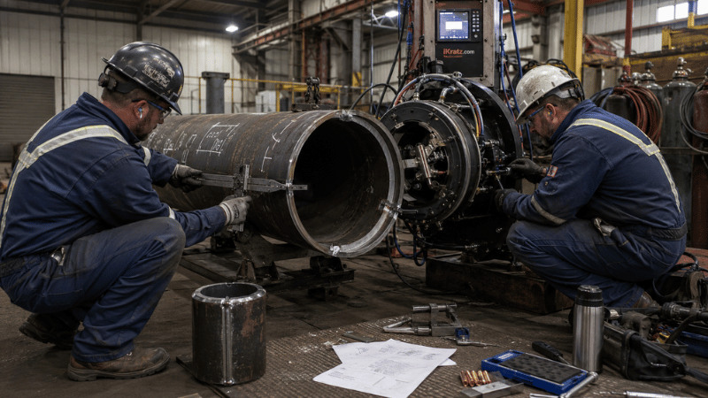
Why Test Welds Matter More Than Demonstrations
A showroom demonstration usually involves clean material, perfect preparation, generous access, and technicians who know the machine better than they know their coffee order.
Production is less polite. Root gaps vary. Pipe ends are not perfectly square. Tack welds intrude into the path. Ovality changes torch-to-work distance, while cables discover exciting new ways to snag.
Representative trials should deliberately include realistic tolerance limits. Examine the effects of hi-low, root-gap variation, tack geometry, surface condition, purge quality, and joint access.
The acceptance plan should identify visual, dimensional, destructive, or nondestructive tests before welding begins. Qualified personnel must also remain involved in equipment setup and parameter control; ISO 14732:2025 addresses qualification requirements for operators and setters working with mechanized and automatic welding systems.
Automatic Versus Manual Pipe Welding
Automatic welding improves repeatability by controlling travel, torch angle, arc length, wire feed, and programmed sectors around the pipe. It can also reduce physical strain and make shift-to-shift output less dependent on an individual welder’s rhythm.
However, manual welding still makes sense for one-off repairs, frequently changing geometry, very low production volumes, and joints where installing automation takes longer than completing the weld.
The sensible question is not, “Which method is faster?” It is, “Which method produces accepted welds at the lowest repeatable cost?”
Calculate annual benefit as labor savings plus added production capacity and avoided rework, minus additional consumables, maintenance, and operating costs. Divide total implementation cost by that annual benefit to estimate payback.
Run low-, expected-, and high-utilization scenarios. Automation purchased for a production forecast that never arrives becomes a remarkably sophisticated coat rack.
Common Problems and Their Real Causes
Inconsistent root penetration is often blamed on the power source, but the usual suspects are fit-up, centering, purge conditions, arc length, or heat-input variation.
Wire-feeding instability may come from liners, contact tips, spool drag, cable routing, or poor synchronization. More software will not repair a crushed liner.
Excessive setup time usually indicates nonstandard tooling, uncontrolled preparation, too many manual adjustments, or weak changeover procedures. Record setup steps during trials and remove unnecessary adjustments before production begins.
Poor operator-to-operator repeatability requires controlled parameter access, documented preparation standards, training, and scheduled maintenance—not merely another reminder taped to the control cabinet.
How to Evaluate a Supplier
A capable supplier should review drawings, material grades, joint geometry, production targets, inspection requirements, and site constraints before recommending equipment.
Ask for representative test welds, parameter records, inspection evidence, training scope, warranty terms, diagnostic support, calibration requirements, and spare-parts availability. A quotation containing only a power source and weld head is rarely the complete project cost.
The broader iKratz orbital welding systems range illustrates why buyers should compare complete configurations rather than isolated components. Controllers, weld heads, cooling, wire feeding, tooling, monitoring, and integration must work as one system.
For an accurate quotation, provide pipe OD, wall thickness, material, bevel drawing, filler wire, production volume, site photographs, available utilities, quality code, inspection method, and current WPS documents. Better input produces better engineering—and considerably fewer awkward emails later.
Conclusion: Selecting the Right Pipe Welding System
The right automatic pipe welding machine must match pipe geometry, material, joint design, access, quality requirements, and production volume. Select the welding process first, then compare complete systems and lifecycle costs.
Most importantly, validate the proposed configuration through representative test welds. The best machine is not the one with the most features; it is the one proven to deliver safe, repeatable, inspectable welds in your actual production conditions.
Build a Welding System Around Your Application
Your project should not be squeezed into a generic machine configuration. iKratz combines application review, orbital welding equipment, automation integration, and technical support to help manufacturers improve consistency without purchasing features they will never use.
Send us your pipe dimensions, material, joint drawing, and production target. Contact us today to request an application review and recommended test-weld plan.
Frequently Asked Questions
What is the difference between orbital and automatic pipe welding?
Orbital welding moves a controlled weld head or carriage around a stationary pipe. Automatic pipe welding is a broader category that also includes robotic cells, internal-diameter machines, track-mounted systems, and fixed workshop equipment.
Which machine is best for large-diameter or thick-wall pipe?
Open orbital heads and track-mounted systems are generally better suited to beveled joints, filler wire, and multi-pass welding. The final choice depends on diameter, thickness, material, access, deposition requirements, and inspection criteria.
How much does an automatic pipe welding machine cost?
Cost depends on the power source, process, weld head, track, wire feeder, cooling system, tooling, monitoring, training, qualification work, and after-sales support. Buyers should compare total implementation and lifecycle costs rather than the base equipment price.
Can one machine weld every pipe size and material?
Usually not. Diameter range, wall thickness, clearance, duty cycle, tooling, shielding, and welding-process limitations make a universal system impractical. A modular platform may cover several applications, but each configuration should be validated on representative joints.