
Arc blow in welding happens when the welding arc refuses to stay on the joint. Instead of tracking straight, it pulls sideways, flares forward, or wanders like it missed the morning briefing.
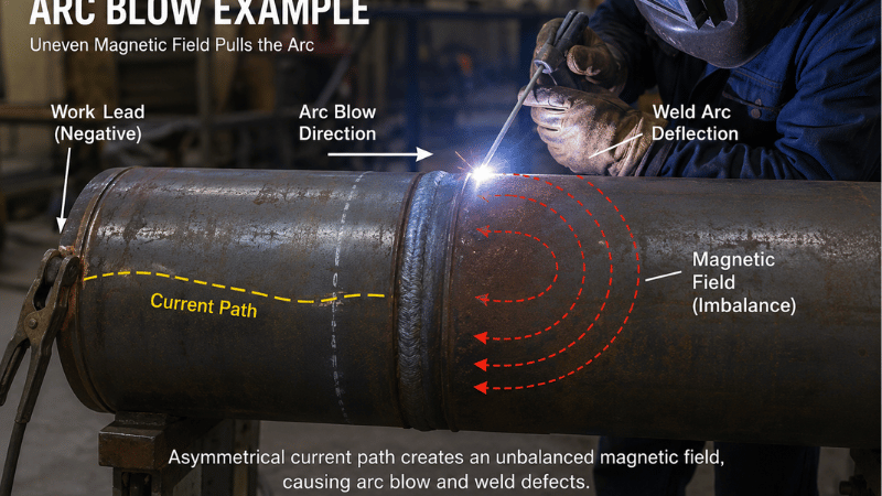
Technically, arc blow is unwanted arc deflection caused by magnetic field imbalance around the welding current. It appears most often in DC welding, but it can also trouble manual welding, automated welding, pipe welding, and orbital welding.
Quick Answer: Arc blow is the unwanted deflection of a welding arc caused by magnetic field distortion. It occurs most frequently in DC welding when the current path creates an unbalanced magnetic force. In industrial welding, arc blow becomes critical when residual magnetism reaches practical risk levels, often around 20 Gauss or higher depending on material, process, and joint geometry.
Why Arc Blow Matters
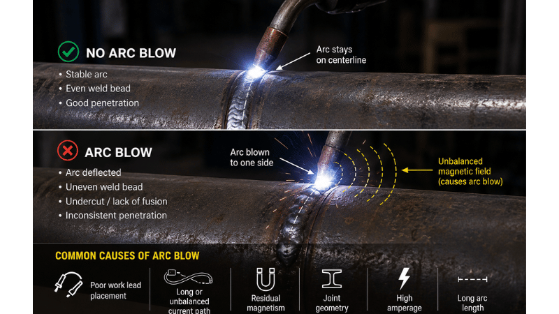
A wandering arc can create undercut, excessive spatter, lack of fusion, inconsistent penetration, porosity, and irregular bead shape. That is not “character.” That is rework with sparks.
In production, welding arc blow becomes expensive fast. One unstable setup can cause failed inspection, lost machine time, repeated operator intervention, and schedule delays—especially when the same defect repeats on an automated welding system.
TWI explains magnetic arc blow as arc wander caused by distortion of the magnetic field produced by welding current.
What Causes Arc Blow?
The root cause is magnetic imbalance. Welding current creates a magnetic field. When that field becomes uneven, the arc moves toward the stronger magnetic influence instead of staying centered in the joint.
Common causes include poor work lead placement, long return-current paths, high amperage, long arc length, joint geometry, tack location, pipe ends, plate edges, corners, and residual magnetism.
Residual magnetism is especially common in pipe, heavy fabrication, and steel handled by lifting magnets or exposed to magnetic inspection. If suspected, use a gauss meter. Guessing is fine for lunch orders, not weld quality.
Arc blow also affects heat input. Even when machine settings are stable, arc deflection changes where the energy lands:Q=η⋅vU⋅I
Here, Q is heat input, η is thermal efficiency, U is arc voltage, I is current, and v is travel speed. When the arc drifts away from the root, effective heat input fluctuates, increasing the risk of poor fusion and uneven HAZ formation.
How to Recognize Arc Blow
The biggest clue is direction. True magnetic arc blow usually pulls the arc toward the same physical direction repeatedly. It may appear near a weld end, tack weld, pipe circumference, plate edge, or high-current pass.
The bead may show one-sided undercut, directional spatter, inconsistent reinforcement, poor tie-in, or a wandering profile. If the defect repeats in the same location, the setup is probably telling you where the problem lives.
Arc Blow vs. Fake Arc Blow
Not every unstable arc is arc blow. The real issue may be poor electrode angle, wrong amperage, contamination, shielding gas problems, poor fit-up, worn consumables, or a loose work clamp.
Try this quick test: adjust the electrode or torch angle briefly. If the arc follows the angle, technique may be the issue. If it keeps pulling toward the same physical direction, true magnetic arc blow is more likely.
| Symptom | Likely Cause | First Fix |
|---|---|---|
| Arc pulls to the same side | Magnetic arc blow | Check work lead and current path |
| Arc changes with electrode angle | Technique issue | Correct travel/work angle |
| Spatter rises near plate end | End-effect arc blow | Change direction or add run-off tab |
| Porosity without arc deflection | Gas or contamination | Check shielding and surface prep |
| Bead wanders with hand movement | Operator control | Shorten arc and stabilize position |
For wider diagnosis, connect this process with your welding defect troubleshooting workflow.
How to Fix Arc Blow
Start with the fastest corrections before changing the welding procedure. First, shorten arc length. A long arc gives magnetic forces more room to shove the arc around.
Next, improve work lead placement. Move the clamp closer when appropriate, clean the contact surface, and avoid long, narrow, or offset return paths.
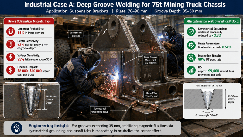
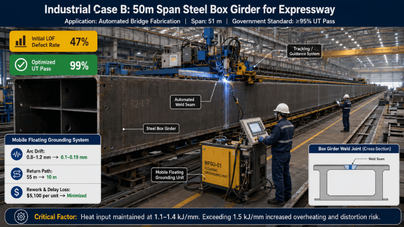
For large workpieces, long seams, pipe, and vessels, use a Symmetrical Grounding Matrix. That means designing balanced return-current paths instead of letting electrons roam around the shop like tourists.
A practical matrix may include dual work leads, mirrored clamp positions, balanced fixture contact points, and equalized return paths on long seams or 6G pipe welds. This is where welding grounding and work lead setup becomes a profit-protection move.
If the WPS allows it, reduce amperage while maintaining required penetration. You can also test weld direction, adjust travel angle, use backstep welding, add tacks, or use run-off tabs near joint ends.
Switching to AC may help because alternating current reduces steady magnetic pull, but only change current type when the machine, consumable, material, code, and approved WPS allow it. The arc may be dramatic, but procedure qualification still runs the show.
If residual magnetism is confirmed, consider demagnetization with proper equipment and qualified personnel. Measure before and after, then document the final setup.
Arc Blow in Automated and Orbital Welding
Manual welders can often compensate by adjusting arc length, angle, speed, or direction. Automated systems cannot “feel” arc blow. They follow the programmed path with heroic confidence—even when the arc is misbehaving.
That makes arc blow especially risky in orbital welding. The torch follows a fixed path around the pipe or tube, so arc deflection can create repeatable defects at the same clock position.
In critical pipe welding quality control, repeated defects are not just weld issues. They are schedule problems with invoices attached. Radiographic testing, explained by ASNT, can reveal internal defects that turn a small setup mistake into a costly repair cycle.
The Hidden Cost of Arc Blow in Automated Lines
| Item | Manual Welding | Automated / Orbital Welding |
|---|---|---|
| Correction ability | Welder can adjust in real time | System repeats programmed path |
| Rework pattern | Often random or local | Often repeatable and batch-wide |
| Production impact | Easier to isolate | May trigger line stoppage |
| 1,000-weld loss example | Approx. $10k–$25k | Approx. $100k–$250k |
If 1,000 welds have a 5% rework rate, that means 50 repairs. At $2,000–$5,000 per repair after labor, inspection, downtime, documentation, and tracking, the loss can reach $100,000–$250,000. Suddenly, that “small arc issue” is wearing a very expensive hat.
Prevention Checklist Before Welding
Before striking the arc, check clamp location, clean contact, cable routing, joint geometry, tack sequence, amperage range, arc length plan, and possible magnetism.
For automated and orbital welding, validate grounding before production. Run trial welds, inspect bead consistency, check whether defects repeat in the same location, and document approved work lead positions.
For critical welds, record current type, polarity, amperage, consumable, work lead position, weld direction, gauss reading, defect type, and inspection result. A setup log beats shop-floor memory every time.
Always follow the approved WPS, machine manual, PPE requirements, ventilation rules, and applicable OSHA welding safety requirements.
Common Pitfalls
Do not increase amperage just to “burn through it.” Higher current can strengthen magnetic effects and make DC welding arc blow worse.
Do not randomly move the work clamp. Move it with a purpose: closer, cleaner, more balanced, or positioned to test whether the arc pull changes.
Do not blame every defect on arc blow. Rust, oil, mill scale, bad gas coverage, wrong parameters, poor fit-up, and worn consumables can cause plenty of chaos by themselves.
FAQs
What is arc blow in welding?
Arc blow is unwanted welding arc deflection, usually caused by magnetic imbalance, DC current effects, poor work lead placement, return-current problems, or residual magnetism.
How do I know if it is real arc blow?
Change the electrode or torch angle briefly. If the arc follows the angle, technique may be the issue. If it keeps pulling toward the same physical direction, magnetic arc blow is more likely.
Can AC welding fix arc blow?
Sometimes. AC can reduce steady magnetic pull, but only use it when the machine, consumable, material, code requirements, and approved WPS allow it.
Why is arc blow serious in orbital welding?
Orbital welding follows a fixed path, so arc deflection can create repeatable defects. That can lead to failed inspection, rework, downtime, and higher production costs
Conclusion
Arc blow is arc deflection caused by magnetic imbalance, poor return-current paths, work lead placement, residual magnetism, joint geometry, or setup conditions. True arc blow usually has a directional pattern; fake arc blow may actually come from technique, shielding gas, contamination, or fit-up problems.
The fastest fixes are shortening arc length, improving work lead placement, using a Symmetrical Grounding Matrix, reducing amperage where allowed, changing weld direction, and checking residual magnetism. In automated and orbital welding, solving arc blow protects weld quality, inspection results, production time, and ROI.
Get Control Before Arc Blow Costs You
When your welds need stable arc behavior, repeatable bead quality, and fewer inspection surprises, setup discipline matters. Our team helps manufacturers review grounding layout, orbital welding stability, residual magnetism risks, and automated welding process conditions before rework quietly eats production margins.
Contact us today to request an arc stability review or discuss your welding setup.

