
Welds can look perfect, right up until they don’t. NDT of welds helps you verify internal quality without cutting anything open, because “destructive testing” is a little too honest for production parts.
RT and UT aren’t rivals. They’re two different ways to see different problems, so the best choice depends on what you’re trying to catch and what your jobsite will actually allow.
Quick Definitions You’ll Actually Use
An indication is “something showed up.”
A discontinuity is “something isn’t uniform.”
A defect is “a discontinuity that violates acceptance criteria.” Your code/spec decides, no matter how persuasive your vibes are.
In a sane QA flow: fit-up → welding → NDT → repair (if needed) → accept/reject.
The Big Picture: Where RT/UT Fit Among NDT Welding Methods
Most weld QA programs mix methods:
- VT catches obvious surface/profile issues early (cheap and underrated).
- PT/MT catch surface-breaking cracks (depending on material).
- RT and UT look for internal issues, but with different strengths.
If you want a general primer, point readers internally to ndt welding methods.
Radiographic Testing (RT) for Welds: How It Works
Radiographic testing (RT) uses X-ray or gamma radiation to create an image of internal conditions. Less dense areas (voids/porosity) usually show stronger contrast, so RT can be very readable for “volume-type” problems.
Typical RT workflow:
- Plan access and shot geometry
- Place source + film/detector
- Expose (film/CR/DR)
- Process/capture image
- Interpret + report
RT’s signature advantage is a visual image record you can store, audit, and review later.
RT safety: the part that changes schedules
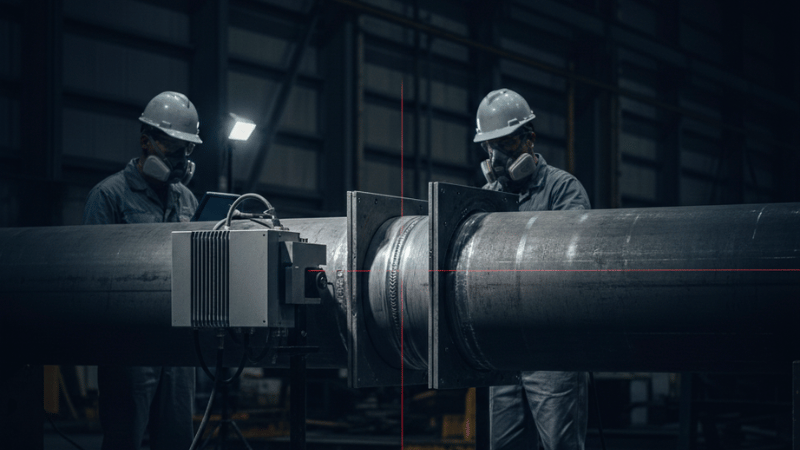
RT requires radiation controls, including exclusion zones, signage, trained personnel, and often off-shift work to avoid exposing others. That’s not “extra.” That’s compliance.
What RT Detects Best (and What It Struggles With)
RT is typically strongest for volumetric indications:
- porosity
- slag inclusions
- voids and some internal profile conditions (geometry dependent)
RT often struggles with tight planar flaws when orientation doesn’t create strong contrast:
- some cracks
- some lack of fusion
- some lack of penetration
If you’ve ever heard “RT missed it” and “UT found it,” planar orientation is usually the plot twist.
Ultrasonic Testing (UT) of Welds: How It Works
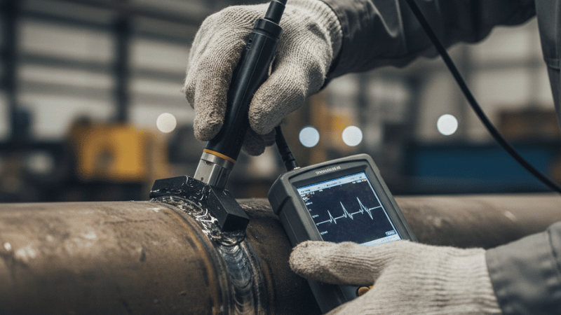
Ultrasonic testing (UT) sends sound waves into the weld and listens for echoes. Discontinuities reflect sound differently than solid metal, letting a technician locate and size indications.
Typical UT workflow:
- Surface prep + couplant
- Probe selection (straight/angle beam)
- Calibration (reference blocks)
- Scan pattern + coverage
- Interpret + report
UT’s signature advantage is that it can be excellent at planar/oriented discontinuities, especially when technique and access are right.
UT variants you may see in specs
- Conventional UT (solid workhorse)
- PAUT (beam steering + richer data)
- TOFD (often used for sizing/planar flaw detection in some applications)
What UT Detects Best (and What It Struggles With)
UT is often strongest for planar/oriented flaws:
- lack of fusion
- lack of penetration
- many crack-like indications (technique/access dependent)
UT can struggle when conditions get unfriendly:
- near-surface “dead zone” effects
- rough caps/geometry that blocks probe movement
- coarse-grained/attenuating materials that scatter sound
- limited access that prevents proper scan angles
Also, UT is more technique/operator dependent, meaning training, calibration, and scan plan matter a lot.
RT vs UT for Weld Inspection: Side-by-Side (Fast Scan)
| Category | RT | UT |
|---|---|---|
| Best at | Volumetric indications | Planar/oriented flaws |
| Record | Image record (film/CR/DR) | Report + (sometimes) stored scan data |
| Safety/logistics | Radiation controls, exclusion zones | No radiation, typical site hazards |
| Access | Often needs source + detector geometry | Often workable from one side (if scan angles possible) |
| Disruption | Can force shutdowns/off-shifts | Usually less disruptive, but scan time varies |
| “Gotchas” | Orientation sensitivity for planar flaws | Geometry/material + operator dependency |
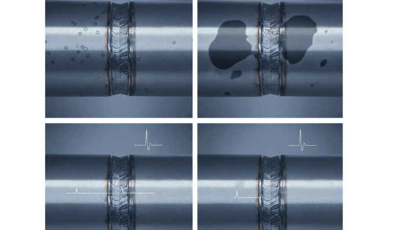
If you remember one thing, RT tends to “see volume.” UT tends to “hear planes.” Both have constraints.
Decision Framework: How to Choose the Right NDT Method
Step 1: What discontinuities are likely?
Process + joint type hint the usual suspects: porosity, slag, lack of fusion, cracks, etc.
Step 2: What constraints are real (not theoretical)?
Access, thickness, curvature, surface condition, site rules, and schedule windows.
Step 3: What’s the risk if you miss it?
Pressure boundary, rotating equipment, high-cycle fatigue zones, safety-critical structures. Risk changes the bar.
Step 4: What does the code/spec actually require?
Acceptance criteria and permitted methods aren’t negotiated on site. They’re decided in the contract, code, and approved procedures.
A simple scoring rubric (quick and defensible)
Score 1 to 5 (5 strongly favors the method):
- Access feasible: RT __ / UT __
- Likely critical flaws are planar: RT __ / UT __
- Radiation constraints: RT __ / UT __
- Need image record: RT __ / UT __
- Schedule disruption tolerance: RT __ / UT __
- Geometry/material UT-friendly: RT __ / UT __
Higher total wins. If it’s close, or consequences are high, consider combined coverage.
Product Spotlight: Orbital Welding Systems Built for RT/UT-Inspectable Welds (ikratz.com)
Inspection success starts upstream with weld consistency. Orbital welding helps by controlling travel, parameters, and repeatability, so you get fewer “mystery rejects” and more predictable NDT outcomes.
At Orbital Welding Systems, iKratz focuses on orbital solutions engineered for consistent weld quality that is well-suited to RT and UT verification under qualified procedures.
Closed Orbital Tube-to-Tube Welding Machine
The Closed Orbital Tube-to-Tube Welding Machine category is designed for controlled tube welding, supporting:
- stable alignment and repeatable travel
- controlled shielding and arc conditions
- reduced variability weld-to-weld
Result: welds that are typically straightforward to evaluate with RT and UT, assuming correct setup and qualified technique.
Open Pipe Welding Head
The Open Pipe Welding Head category targets pipe applications where access and geometry vary. It supports:
- controlled orbital movement around the joint
- repeatable parameters across similar welds
- efficient production welding with inspection in mind
In normal operating conditions, and when procedures, fit-up, shielding, and operator practices are followed, these welds are generally highly compatible with both RT and UT inspection programs.
Audit-safe note: no system can promise “always passes” because procedures, operators, material condition, and environment still matter. Orbital systems can dramatically reduce variability, which is the number one ingredient in surprise NDT failures.
Defect-to-Method Mapping (Quick Reference)
| Defect type | RT | UT | Notes |
|---|---|---|---|
| Porosity | High | Med | RT often very readable |
| Slag inclusions | High to Med | Med | Orientation/size matters |
| Lack of fusion | Low to Med | High | UT advantage for planar reflectors |
| Lack of penetration | Low to Med | High | UT often preferred if access allows |
| Cracks | Low to Med | High | UT + surface methods can complement |
| Geometry/profile issues | VT first | UT/RT second | Don’t let NDT be your first look |
Conclusion
RT is best for volumetric indications and leaves a clear image record, but it adds radiation logistics. UT is best for planar flaws and avoids radiation, but it’s more technique dependent.
Choose based on risk, access, geometry/thickness, schedule, record needs, and code/spec rules. Consistent orbital welding can make RT/UT outcomes more predictable.
Take the Next Step
Repeatable Orbital Welds, Not Guesswork
When quality matters, don’t rely on “close enough.” Orbital welding delivers consistent travel, shielding, and fit-up control, so results stay stable shift to shift.
➡️ Visit Our Website to Explore Orbital Welding Systems
Talk to People Who Plan for RT and UT
We’ll match your material, OD/WT, joint type, access limits, and code/spec to the right orbital setup, plus an inspection-friendly RT/UT plan that cuts rework and surprises.
➡️ Submit an Inquiry & Your Project Details Today
Frequently Asked Questions
1) Which is better for weld inspection, RT or UT?
Neither is “always better.” RT often excels at volumetric indications and produces image records, while UT often excels at planar/oriented flaws and avoids radiation. The best choice depends on constraints, risk, and code/spec requirements.
2) Can UT replace radiography for welds?
Sometimes, if the project code/spec allows it and procedures/personnel are qualified for the weld type, thickness, and access conditions. Advanced UT (like PAUT) may be accepted in some cases, but approval is client/spec driven.
3) What defects can RT miss that UT can find (and vice versa)?
RT can struggle with tight planar flaws depending on orientation, while UT can struggle with some volumetric indications and challenging geometry/material conditions. A defect-to-method matrix helps reduce blind spots.