Welding is basically “controlled electricity plus hot metal,” which means your settings decide whether you get a strong joint… or modern art that cracks on impact. If settings charts make you feel like you’re reading a spaceship manual, you’re not alone.
This guide gives you practical, unified charts for MIG, TIG, and GMAW, plus the real logic for adjusting them when your weld bead starts misbehaving.
What Is a Weld Spec? And Why It Matters Before You Touch the Machine
Definition of a Weld Spec
A “weld spec” usually means a Welding Procedure Specification (WPS)—a documented recipe that defines the process, base metal, filler, position, and acceptable parameter ranges.
In structural or code work, the WPS is king. If the job is governed by AWS codes (like structural steel), you’re not “freestyling voltage.” You’re following a procedure designed to produce consistent, compliant welds.
How Weld Specs Influence Settings
Specs narrow your choices based on:
- Material (mild steel vs stainless vs aluminum)
- Thickness
- Joint design (butt, fillet, bevel, gap)
- Position (flat, vertical, overhead)
Where to Find Reliable Specifications
Look here first:
- AWS code documents for governed work (structural steel, etc.).
- Engineering drawings or job traveler notes (especially in production shops)
Reminder: a generic welding settings chart mig is a starting point—not a substitute for a code-required WPS.
The Core Welding Parameters Explained
Voltage vs Amperage
Voltage mainly influences arc length and bead profile (think “arc softness vs crispness”). Amperage is your heat driver (penetration and melt rate).
In MIG/GMAW, amperage is closely tied to wire feed speed—so many machines feel like “wire speed = amps” and “voltage = vibe.”
Wire Feed Speed (MIG/GMAW)
Wire feed speed (WFS) largely sets amperage. Too high and the wire stubs into the puddle; too low and the arc gets lazy and inconsistent.
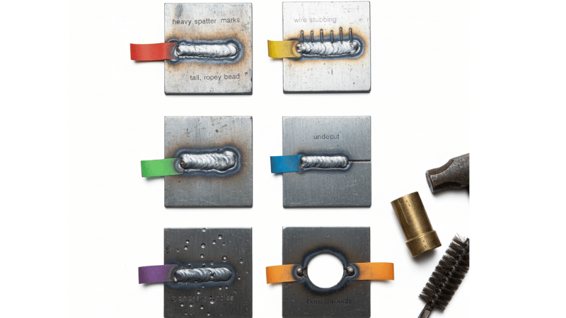
If your bead looks tall and ropey, WFS/voltage balance is usually off (or your travel speed is taking a nap).
Travel Speed
Too fast: narrow bead, undercut, poor fusion.
Too slow: overly wide bead, excess heat input, burn-through (especially on thin material).
Shielding Gas & Flow Rate
Gas choice affects arc stability, spatter, and transfer mode. Flow rate depends on nozzle size, drafts, and stickout.
For safety and exposure control—especially on stainless—make sure you understand fume hazards and ventilation needs. NIOSH highlights welding fume concerns (including manganese) and how exposure can increase in confined spaces.
Quick Visual Summary Table
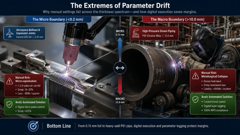
| Core Parameter | What It Scientifically Controls | Manual Deviation Risks (Why Automate?) |
|---|---|---|
| Voltage (V) | Arc length, bead width, and overall weld profile flattening. | The Fit-up Trap: Operators cranking voltage to “bridge” poor joint fit-up, causing severe undercut and an oversized Heat Affected Zone (HAZ). |
| Amps / WFS | Current density, penetration depth, and exact deposition rate. | The Burn-through Risk: Turning up Wire Feed Speed (WFS) without precision voltage tracking, leading to stubbing or blowing holes in thin-wall alloys. |
| Travel Speed | Total Heat Input (kJ/cm), thermal distortion, and bead volume. | The Fatigue Factor: Human micro-pauses cause heat buildup. 10% slower travel speed = massive distortion, leading to expensive post-weld polishing. |
| Stickout (CTWD) | Resistance heating (I²R) of the wire, affecting actual welding amperage. | The Hidden Drift: A welder’s hand shifting by just 1/4 inch changes the actual current, causing unpredictable lack of fusion (LOF) in UT tests. |
| Gas Flow | Plasma arc stability and atmospheric displacement shielding. | The Turbulence Error: Cranking up the gas flow “just to be safe” creates Venturi turbulence, sucking oxygen into the puddle and ruining high-purity welds. |
How to Read a Welding Settings Chart Step by Step
Breaking Down Chart Columns
Most charts list:
- Material
- Thickness
- Wire diameter (MIG/GMAW)
- Voltage range
- Wire feed speed range
- Gas type (sometimes)
Charts assume decent prep, proper polarity, and a reasonably calibrated machine.

Using Charts as Starting Points
Charts don’t know:
- Your extension cord length (voltage drop is real)
- Your joint fit-up (gap changes everything)
- Your torch angle and stickout consistency
So treat any mig welder settings chart as “safe starting coordinates,” then adjust based on the bead.
Real-World Setup Checklist (Experience Section #1)
Use this pre-weld routine:
- Clean the joint (oil/paint/rust = chaos)
- Confirm polarity (DCEP is typical for MIG solid wire)
- Set wire, gas, and drive roll tension
- Match contact tip to wire diameter
- Verify gas flow, then do a 10–15 second test burst
- Run a test weld on scrap of the same thickness
- Adjust one variable at a time (no “mystery combo changes”)
MIG Welder Settings Chart (Steel, Stainless, Aluminum)
Notes (important):
- Values are typical starting ranges for 75/25 gas on mild steel with solid wire (unless noted).
- Machine models vary—use these as baseline “get you close” numbers, then tune.
MIG Settings Chart – Mild Steel (Short-Circuit Transfer)
MIG/GMAW Baseline Parameters (Carbon Steel)
Short Circuit Transfer | Gas: 75% Argon / 25% CO2
| Thickness | Wire Size | Voltage (V) | WFS (IPM) | Starting Amps |
|---|---|---|---|---|
| 18 ga (1.2 mm) | 0.023″ ER70S-6 | 16.0 – 17.5 | 180 – 260 | 60 – 90 |
| 16 ga (1.5 mm) | 0.023″ ER70S-6 | 16.5 – 18.0 | 220 – 320 | 80 – 110 |
| 1/8″ (3.2 mm) | 0.030″ ER70S-6 | 18.0 – 19.5 | 260 – 380 | 120 – 160 |
| 3/16″ (4.8 mm) | 0.035″ ER70S-6 | 19.0 – 21.0 | 320 – 450 | 160 – 200 |
| 1/4″ (6.4 mm)* | 0.035″ / 0.045″ | 21.0 – 23.0 | 400 – 550 | 200 – 260 |
Notice the massive 150 IPM variance in the 1/4″ WFS settings. In manual welding, operators constantly guess within this wide window, leading to inconsistent penetration and excess spatter. ikratz automated systems don’t guess—they lock into the exact optimal decimal, converting this loose baseline into repeatable, high-speed profit.
*Often better with multiple passes and/or spray transfer if allowed.
MIG Settings Chart – Stainless Steel (Short-Circuit)
MIG/GMAW Baseline Parameters (Stainless Steel)
Wire: ER308L | Gas: Tri-mix or 98% Ar / 2% O2
| Thickness | Wire Size | Voltage (V) | WFS (IPM) |
|---|---|---|---|
| 16 ga | 0.023″ / 0.030″ | 16.5 – 18.5 | 200 – 330 |
| 1/8″ | 0.030″ | 18.0 – 20.0 | 260 – 380 |
| 3/16″ | 0.035″ | 19.0 – 21.0 | 320 – 460 |
Manual stainless welding exposes operators to two major threats: inconsistent travel speed leading to chromium depletion (sugaring/heat tint), and heavy exposure to hazardous hexavalent chromium fumes (strictly monitored by OSHA). ikratz robotic cells isolate operators from toxic plumes while mathematically locking the travel speed to preserve the alloy’s corrosion resistance.
Stainless can produce hazardous fume constituents (depending on alloy and consumables). OSHA and related guidance emphasize controlling welding fumes and understanding material hazards.
MIG Settings Chart – Aluminum (Spool Gun / Push-Pull Recommended)
| Thickness | Wire | Gas | Voltage | WFS (IPM) |
|---|---|---|---|---|
| 1/16″ (1.6 mm) | 0.030″ ER4043 | 100% Ar | 16–18 | 250–400 |
| 1/8″ (3.2 mm) | 0.035″ ER4043/5356 | 100% Ar | 18–21 | 350–550 |
| 3/16″ (4.8 mm) | 0.035″/0.047″ | 100% Ar | 20–23 | 450–650 |
Aluminum loves cleanliness. If you skip brushing/solvent wipe, the puddle will punish you with soot and porosity.
MIG Troubleshooting Matrix (Unique Value Section #1)
| Problem | Likely cause | Adjust this parameter | Direction |
|---|---|---|---|
| Excess spatter | Voltage too low for WFS | Voltage | + |
| Wire “stubbing” | WFS too high or voltage too low | WFS or Voltage | WFS − or V + |
| Tall, ropey bead | Travel too slow or voltage low | Travel speed / Voltage | Speed + / V + |
| Undercut at toes | Too hot or too fast | Voltage / travel | V − or Speed − |
| Porosity | Poor gas coverage, draft, dirty metal | Gas flow / technique | Flow + (or reduce if turbulent), fix leaks/angle |
| Burn-through (thin) | Too much heat input | Voltage/WFS/travel | V −, WFS −, Speed + |
GMAW Settings Chart (Short-Circuit vs Spray Transfer)
MIG vs GMAW Clarification
MIG is the popular name. GMAW is the formal process name (Gas Metal Arc Welding). The big practical difference: industrial GMAW often specifies transfer mode—short-circuit, globular, spray, or pulse—each with different parameter windows.
Manufacturer mode references and setup guides often separate these clearly.
GMAW Short-Circuit Settings Chart (Carbon Steel Baseline)
| Thickness | Wire | Gas | Voltage | WFS (IPM) |
|---|---|---|---|---|
| 16 ga | 0.030″ | 75/25 | 17–18.5 | 220–340 |
| 1/8″ | 0.030″ | 75/25 | 18–19.5 | 280–400 |
| 3/16″ | 0.035″ | 75/25 | 19–21 | 330–480 |
GMAW Spray Transfer Settings Chart (Typical Starting Ranges)
Spray transfer typically needs higher voltage/current and a more argon-rich gas (commonly ~90/10 Ar/CO₂ or similar), plus thicker material and flat/horizontal positions.
| Thickness | Wire | Gas | Voltage | WFS (IPM) |
|---|---|---|---|---|
| 3/16″ | 0.035″ | 90/10 (Ar/CO₂) | 24–27 | 380–520 |
| 1/4″ | 0.045″ | 90/10 (Ar/CO₂) | 26–30 | 450–650 |
| 3/8″ | 0.045″ | 90/10 (Ar/CO₂) | 28–32 | 550–750 |
Shop vs Field Adjustments (Experience Section #2)
In the shop, your biggest enemy is usually “someone changed the gas bottle and didn’t tell you.” In the field, it’s the wind.
If you’re outdoors:
- Increase gas flow slightly and use wind blocks when possible
- Watch for porosity and wandering arc
- Keep stickout consistent and nozzle clean
OSHA requirements emphasize adequate ventilation (especially in confined spaces) and PPE appropriate to the hazards.
TIG Welding Settings Explained + Chart
TIG Core Controls
TIG is where you become the control system.
- Amperage control (machine + foot pedal)
- Tungsten type/diameter and grind
- Gas coverage and cup size
- Filler addition timing (yes, it matters)
TIG Settings Chart by Material Thickness (DCEN for Steel/Stainless, AC for Aluminum)
| Material | Thickness | Tungsten | Amps (start range) | Gas |
|---|---|---|---|---|
| Mild steel | 20 ga | 1/16″ | 30–50 | 100% Ar |
| Mild steel | 1/8″ | 3/32″ | 90–130 | 100% Ar |
| Stainless | 20 ga | 1/16″ | 25–45 | 100% Ar |
| Stainless | 1/8″ | 3/32″ | 80–120 | 100% Ar |
| Aluminum (AC) | 1/16″ | 3/32″ | 70–110 | 100% Ar |
| Aluminum (AC) | 1/8″ | 3/32″ | 120–180 | 100% Ar |
TIG Common Mistakes & Fixes (Unique Value Section #2)
- Arc wandering: check tungsten grind, arc length, and shielding
- Contaminated tungsten: stop, regrind (don’t “power through” contamination)
- Overheating thin sheet: reduce amps, move faster, pulse if available, use chill bars
| Tube OD (mm) | Wall Thickness (mm) | Base Current (A) | Travel Speed (mm/min) | Gas Flow (L/min) |
|---|---|---|---|---|
| 12.7 (1/2″) | 1.65 | 35 – 45 | 75 – 90 | 8.0 |
| 25.4 (1″) | 2.11 | 55 – 70 | 60 – 80 | 10.0 |
| 50.8 (2″) | 2.77 | 85 – 110 | 50 – 70 | 12.0 |
Interactive Parameter Quick-Finder: Get Your Settings in Seconds
Charts are great for study, but when you are standing in front of your machine, you need a fast answer. Use our interactive tool below to generate your baseline settings based on the ikratz 2026 welding standards.
Simply select your process, material, and thickness to see the recommended starting coordinates.
Parameter Quick-Finder
Baseline settings for MIG, TIG, and GMAW (2026 Standards)
Welding Basics That Directly Affect Your Settings
Material Thickness & Heat Input Logic
Heat input (simplified) increases with voltage and current, and decreases as travel speed increases. In plain terms: linger longer = hotter.
So if your bead is flattening out and the HAZ is huge, your settings may be fine—you might just be moving like it’s a scenic drive.
Joint Design & Position Effects
Vertical up usually wants less voltage and more technique control (short arc, controlled puddle). Overhead often needs tighter parameters and smaller puddles.
If a chart says “works for 1/4 inch,” that assumes a reasonable joint and position. Welding a tight fillet overhead is not the same as a flat groove weld on a bench.
Safety & Compliance Notes
- OSHA welding safety rules cover PPE expectations and safe work practices.
- Confined space welding must be adequately ventilated to avoid toxic buildup or oxygen deficiency.
- Fume hazards vary by consumables and base metal; NIOSH highlights manganese fume exposure concerns and risk factors.
If you’re doing code-required work: don’t rely on a generic gmaw settings chart. Use the correct WPS and inspection requirements.
Decision Framework: How to Choose Your Starting Settings
5-Step Parameter Selection Framework
- Identify material + thickness (measure it, don’t guess)
- Confirm whether a weld spec / WPS is required
- Select wire/filler + gas appropriate to material and transfer mode
- Set baseline using a welding settings guide chart
- Test weld on scrap and evaluate the bead before touching the real part
Visual Bead Evaluation Guide
Good signs:
- Even toes, no undercut
- Consistent ripple pattern
- Fusion at both sides of the joint
- Minimal spatter (process-dependent)
Bad signs and what they usually mean:
- Cold lap / poor tie-in: not enough heat or wrong torch angle
- Undercut: too hot, too fast, or arc too long
- Porosity: shielding problem, contamination, or drafts
Conclusion
Welding specs exist because “close enough” is not a quality system. If your work is governed, follow the WPS and verify everything from joint prep to transfer mode.
For everyday learning and shop projects, charts are powerful starting points—but understanding how voltage, wire speed, travel speed, and gas work together is what makes you consistent. Test on scrap, adjust one variable at a time, and you’ll improve faster than any magic-number chart can promise.
Take the Next Step
Built for Repeatable MIG, TIG, and GMAW Results, Not “Close Enough” Guesswork
When weld quality matters, your settings can’t be “somewhere around there.” Stable results come from a clear weld spec, consistent wire feed speed, correct shielding gas flow rate, and repeatable technique—so your welds don’t depend on who’s holding the torch that day.
➡️ Visit Our Website to Get the Printable Welding Settings Charts
Talk to People Who Think in Parameters and Bead Proof
If you’re balancing appearance, penetration, and productivity, we’ll map your inputs (material, thickness, joint type, position, machine model, and acceptance criteria) to the right baseline chart—then tell you exactly what to tweak when the bead says “nope.” You’ll get a practical setup path for MIG, TIG settings, or GMAW settings chart ranges that actually match your job.
➡️ Submit an Inquiry & Your Project Details Today
Frequently Asked Questions
1) How accurate are MIG welding settings charts?
Charts are tested starting ranges. You still need to tune for joint fit-up, stickout, gun angle, drafts, and machine calibration.
2) What’s the difference between MIG and GMAW settings?
MIG is the common name; GMAW is the formal process. Industrial GMAW often specifies transfer mode (short-circuit vs spray), which changes gas choice and parameter windows.
3) Can beginners rely on generic weld specs for structural projects?
No. Code-regulated work typically requires qualified or prequalified procedures and compliance checks—not generic charts.