
Choosing MIG wire should not feel like reading an ancient welding prophecy. This MIG wire size chart gives you a practical starting point by metal thickness, welder output, shielding gas, and project type.
Wire diameter affects penetration, deposition rate, bead control, spatter, burn-through risk, and machine load. Always confirm your welder manual and test on scrap metal first.
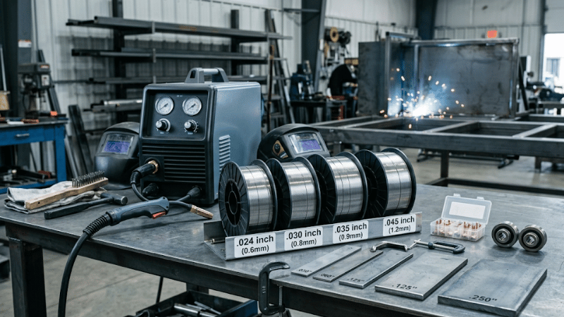
Quick MIG Wire Size Chart by Metal Thickness
For most mild steel MIG welding, start here:
Quick MIG Wire Size Chart: Mild Steel Basics
| Metal Thickness | Recommended Wire Size | Primary Application / Best Use |
|---|---|---|
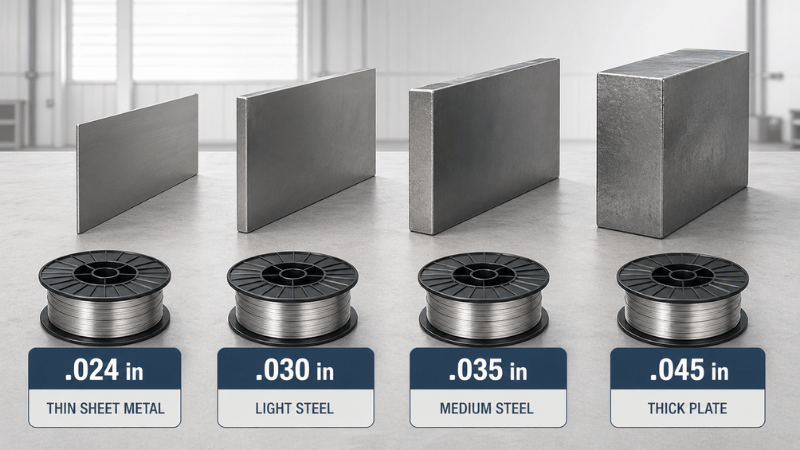
| Under 1.2 mm (Thin Sheet) | .024 in (0.6 mm) | Auto body, delicate sheet metal work |
| 1.2 – 3 mm | .030 in (0.8 mm) | DIY repairs, general garage projects |
| 3 – 6 mm | .035 in (0.9 mm) | Brackets, frames, medium-duty steel |
| Over 6 mm (Heavy Plate) | .045 in (1.2 mm) | Thick plate welding, heavy industrial fabrication |
This chart assumes solid MIG wire on mild steel. For aluminum, stainless steel, flux-cored wire, or code-critical work, confirm the full setup instead of trusting one chart like it owes you money.
Full MIG Wire Size Chart by Setup
Full MIG Wire Size & Technical Setup Chart
| Metal Thickness | Wire Size | Common Use | Shielding Gas | Transfer Mode | Setup Caution |
|---|---|---|---|---|---|
| 24–20 ga sheet | .024 in | Auto body panels | C25 | Short circuit | Avoid burn-through |
| 18–14 ga sheet | .024–.030 in | Thin frames, panels | C25 | Short circuit | Control heat input |
| 1/8 in steel | .030–.035 in | DIY repair, brackets | C25 or CO₂ | Short circuit | Check penetration |
| 3/16 in steel | .035 in | Small fabrication | C25 or CO₂ | Short circuit/globular | Watch duty cycle |
| 1/4 in steel | .035–.045 in | Trailer repair, plate | CO₂ or Ar/CO₂ | Short circuit/spray | Bevel or multi-pass |
| 5/16 in+ steel | .045 in | Heavy fabrication | CO₂ or Spray gas | Spray-capable | Confirm capacity |
For mild steel, C25 shielding gas is commonly used for smoother short-circuit welding, while CO₂ can improve penetration but often increases spatter.
What MIG Wire Size Actually Means
MIG wire size means wire diameter, not spool size. A 2 lb spool and an 11 lb spool can both carry .030 wire.
Common MIG welding wire sizes include .024, .030, .035, .040, and .045 inch. Smaller wire gives better control on thin metal. Larger wire carries more current, deposits more filler metal, and usually needs more welder output.
In plain shop language, wire size changes how hot, fast, smooth, and forgiving the weld feels.
.024 vs .030 vs .035 vs .045 MIG Wire
Use .024 MIG wire for thin sheet metal, auto body panels, and parts where burn-through is the main enemy. It works well with lower amperage and gives better puddle control.
Use .030 MIG wire for general DIY welding, light-to-medium steel, many 120V welders, and beginner garage projects. For home welders, .030 is often the sweet spot.
Use .035 MIG wire for 1/8 inch to 1/4 inch steel when your welder has enough amperage. It deposits more metal than .030 wire, but it also creates more heat and machine load.
Use .045 MIG wire for thick plate, farm repair, heavy fabrication, and production welding with capable 240V or industrial machines. For spray transfer, the whole setup must support it: voltage, amperage, shielding gas, machine capacity, and welding position.
Wire Size, Deposition Rate, and Real Welding Cost
Wire size is not only about “can it weld this thickness?” It also affects deposition rate, meaning how much filler metal you can place into the joint over time.
Moving from .035 to .045 wire can improve productivity when the machine has enough amperage. But it can also raise heat input, gas use, consumable wear, and power demand. Bigger wire can save time—or just help you make expensive spatter faster.
For production welding, judge MIG wire size by total welding cost: labor time, rework, spatter, downtime, consumable life, and weld quality.
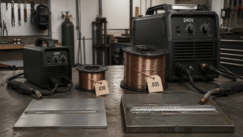
120V vs 240V Welders: Why Power Matters
A 120V welder often performs best with .030 wire because it provides useful deposition without demanding too much current. It is practical for home repair, thin-to-medium steel, and beginner projects.
A 240V welder has more amperage headroom and usually a better duty cycle, making it better suited for .035 and .045 wire, longer welds, and thicker steel.
If your welder keeps shutting down, it may not be moody. Larger wire may simply be pushing the machine past its duty cycle.
MIG Wire Size for Mild Steel, Stainless Steel, and Aluminum
For mild steel, use .024 for thin sheet, .030 for general repair, .035 for medium steel, and .045 for heavy work with capable equipment.
For stainless steel, match the filler wire grade to the base metal and control heat input carefully. Stainless can distort more easily than mild steel, so bigger wire is not always better.
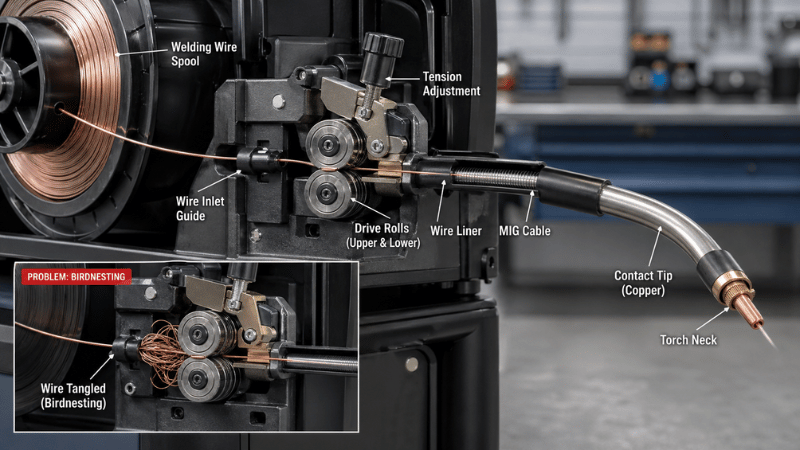
For aluminum, feeding is the big challenge. Aluminum wire is soft and more likely to birdnest, especially through a long standard MIG gun. A spool gun or push-pull setup may be needed.
Wire Diameter and Transfer Modes
Short-circuit transfer is common with .024, .030, and .035 wire. It works well for thinner material, lower heat input, and many out-of-position welds.
Spray transfer is usually used for thicker material, higher deposition, and flat or horizontal welding. It requires suitable amperage, voltage, shielding gas, and machine capability.
That is why the same welding wire size can behave differently on two machines. Wire diameter is only one part of the setup.
Best MIG Wire Size by Project Type
For sheet metal, use .024 or .030 wire. Keep heat low, weld in short sections, and move around the panel to reduce distortion.
For 1/8 inch steel, use .030 or .035 wire. Choose .030 for smaller machines and easier control; choose .035 for faster fill with enough output.
For 1/4 inch steel, use .035 or .045 wire depending on machine capacity. Beveling, joint prep, and multi-pass welding may matter more than simply increasing wire size.
For auto body work, .024 wire is often safest. For farm and equipment repair, .035 or .045 wire is common, but clean rust, paint, oil, and grease first.
Heat Input, Distortion, and Thin Parts
On thin sheet metal, the goal is not maximum deposition. The goal is controlled heat input.
Smaller wire, such as .024 or sometimes .030, allows lower amperage and a smaller weld puddle. That helps reduce burn-through, warping, extra grinding, and rework.
Think of it like cooking with a smaller flame. You may move slower, but you are less likely to burn dinner—or in this case, a customer’s panel.
Field Insight: 20% Reduction in Heat-Affected Zone (HAZ)
In a 1.2mm stainless steel panel project, switching from .030 to .024 wire allowed for a tighter short-circuit transfer at lower voltages.
- Result 1: Global temperature of the panel stayed below 60°C.
- Result 2: Longitudinal shrinkage was reduced by 18%, preventing the “waviness” common in thin-gauge fabrication.
Common MIG Wire Size Mistakes
Using wire that is too large can cause burn-through, poor puddle control, excess heat input, and machine overload.
Using wire that is too small can cause slow deposition, poor penetration, and too many passes on thicker steel.
Forgetting consumable compatibility is another classic mistake. Your contact tip, liner, and drive roll must match the wire diameter and wire type.
In automated welding, robotic cells, long cable systems, or drum-pack feeding, feeding consistency becomes just as important as arc performance. Wire stiffness, cast, helix, liner condition, drive-roll pressure, and spool tension all affect how smoothly wire reaches the arc.
A wire that feeds nicely from a small spool may behave differently in a 250 kg drum or long-distance feed setup. That is where “cheap wire” can become very expensive.
Troubleshooting Chart by Weld Symptom
| Symptom | Possible Cause | Fix |
|---|---|---|
| Burn-through | Wire too large, voltage too high, slow travel | Use smaller wire, reduce heat, stitch weld |
| Poor penetration | Wire too small, low voltage, fast travel | Increase heat, bevel joint, use larger wire |
| Excess spatter | Wrong settings, dirty metal, poor gas coverage | Adjust settings, clean metal, verify gas |
| Birdnesting | Wrong tension, liner mismatch, soft wire | Adjust drive roll, liner, or use spool gun |
| Duty-cycle shutdown | Wire too large or long weld time | Reduce load, use smaller wire, allow cooling |
Welding safety is not optional. Use proper PPE, ventilation, fire protection, and electrical safety practices.
MIG Wire and Consumables Buying Guide
When buying MIG wire, also check matching contact tips, drive rolls, liners, nozzles, shielding gas, and polarity requirements.
Small spools are smart for testing a new wire size. Larger spools make sense once you confirm compatibility with your welder, material, gas, and project type.
Store wire dry and clean. Rusty wire contaminates welds, wears liners, and ruins consistency. Your welder wants clean wire, not archaeological findings.
MIG Wire Size Decision Framework
MIG Wire Size Decision Framework: Professional Selection Guide
| Selection Factor | Engineering Checklist & What to Check |
|---|---|
| Metal Thickness | Determine base metal gauge. Use .024″ for thin sheet (< 1.2mm) and .045″ for heavy plate (> 6mm). |
| Welder Output | Check input voltage. 120V machines favor .030″ wire; 240V/Industrial units are required for stable .045″ arc performance. |
| Duty Cycle | Verify machine limits. Larger wire demands more current; ensure the Duty Cycle (e.g., 60% at 200A) supports the required weld length. |
| Welding Position | Assess gravity impact. Smaller wires (.030″-.035″) are easier to control for Vertical or Overhead welding in short-circuit mode. |
| Material Type | Match wire chemistry (e.g., ER70S-6 for mild steel). Aluminum requires specialized drive rolls and typically larger diameters for feed stiffness. |
| Production Goal | Balance Precision vs. Deposition. Choose smaller wire for detail/aesthetic control; larger wire for maximum filler volume per hour. |
Beginner path: use .024 for thin sheet metal, .030 for general DIY and many 120V welders, .035 for thicker steel when supported, and .045 for heavy work with capable 240V or industrial equipment.
FAQs
Is .030 or .035 MIG wire better?
.030 wire is usually better for thinner metal, smaller welders, and general DIY use. .035 wire is often better for thicker steel, higher amperage, and faster deposition.
Can I use .035 MIG wire in a 120V welder?
Only if your welder manual supports it. Many 120V welders perform better with .030 wire because .035 wire can demand more amperage and may trigger feed issues or duty-cycle limits.
What MIG wire size should I use for 1/8 inch steel?
Use .030 or .035 wire. Choose .030 for smaller machines and easier control. Choose .035 if your welder has enough output and wants more deposition.
What MIG wire size should I use for aluminum or stainless steel?
Aluminum and stainless need material-specific setup decisions. Aluminum may need a spool gun or larger/stiffer wire for reliable feeding, while stainless usually needs tighter heat control to avoid distortion.
Conclusion
This MIG wire size chart helps you choose the right starting point, but the best wire size depends on more than metal thickness. Welder output, duty cycle, shielding gas, transfer mode, feeding consistency, heat input, and deposition rate all affect the final result.
Use .024 for thin sheet metal, .030 for DIY and many 120V welders, .035 for medium steel, and .045 for thick plate or production welding. If your goal is higher output, compare bead size with rework, spatter, consumable wear, downtime, and total welding cost.
Need the Right MIG Wire and Consumables?
Choosing MIG wire is not just about diameter. The right wire, contact tips, drive rolls, liners, shielding gas, and feeding setup can improve weld quality, reduce downtime, and help your team control real production cost—not just spool price.
Contact us today to find the right MIG wire and consumables for your welder, material thickness, production volume, and application.


