Choosing a cladding process is not a contest to find the machine with the biggest deposition-rate number. The real challenge is balancing productivity, dilution, alloy chemistry, surface finish, geometry, and total cost.
This guide compares hot-wire TIG vs cold-wire TIG and PTA cladding so you can shortlist the right process without turning an expensive component into an equally expensive metallurgy experiment.
What Is a Weld Overlay Process?
A weld overlay process deposits a metallurgically bonded alloy layer onto a base material. The deposited layer may improve corrosion resistance, wear resistance, heat resistance, or restore dimensions on a worn component.
Weld overlay is the broad application category. TIG cladding, PTA cladding, submerged arc cladding, and laser cladding are different ways to create that protective layer.
According to TWI’s technical overview of cladding, weld cladding can be applied through GTAW, PTAW, GMAW, SAW, and other processes. TWI also highlights substrate dilution as a major influence on final corrosion performance.
Cladding should not be confused with hardfacing or buttering. Cladding usually adds corrosion-resistant material, while hardfacing targets abrasion, impact, erosion, or metal-to-metal wear. Buttering creates an intermediate layer to improve weldability or manage metallurgical incompatibility.
How TIG Cladding Works
TIG, also called GTAW, uses a non-consumable tungsten electrode to create the arc. Filler wire enters the weld pool separately, giving the process unusually precise control over heat, wire placement, and bead shape.
That control makes TIG cladding popular for valves, pipe bores, flanges, pressure components, turbine parts, and nickel-alloy overlays. It is especially useful when final chemistry matters more than winning a “kilograms per hour” beauty contest.
Overlay quality depends on travel speed, current, wire-feed rate, arc length, torch angle, bead overlap, and interpass temperature. Change one variable carelessly, and several others may follow it off a cliff.
For a deeper equipment-focused explanation, see the iKratz TIG cladding machine selection guide, which covers machine configuration, ID and OD access, automation features, factory acceptance testing, and production-cycle measurement.
Hot-Wire TIG vs Cold-Wire TIG
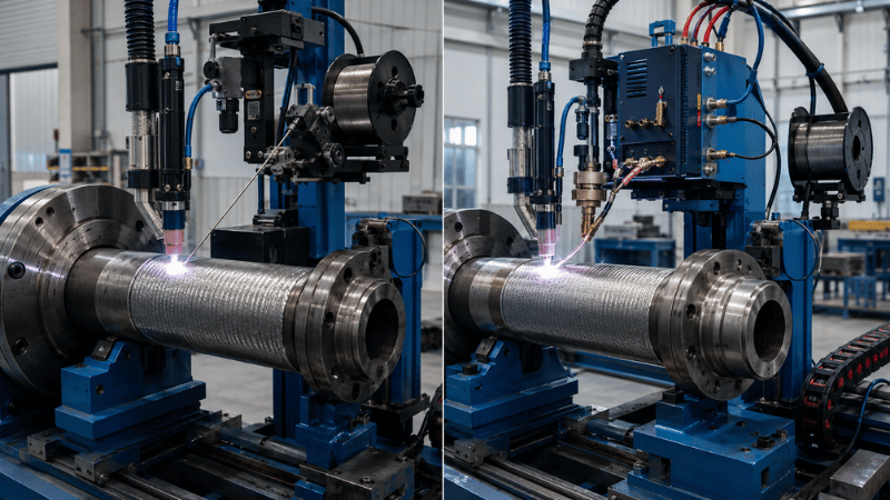
The core difference in hot-wire TIG vs cold-wire TIG is what happens to the filler wire before it reaches the weld pool.
Cold-wire TIG feeds unheated filler into the pool. The arc must melt both the substrate surface and the incoming wire. Equipment is comparatively straightforward, and operators have excellent control over small pools, narrow areas, repairs, and irregular geometry.
Hot-wire TIG passes electrical current through the filler wire, resistance-heating it before deposition. Because the wire arrives already hot, less arc energy is required to melt it, allowing higher wire-feed rates without automatically increasing substrate melting.
Side-by-Side TIG Comparison
Cold-Wire TIG vs Hot-Wire TIG
Quick comparison of control, deposition, complexity, and production fit.
| Selection Factor | Cold-Wire TIG | Hot-Wire TIG |
|---|---|---|
| Deposition capability | Lower | Higher |
| Process control | Excellent | Excellent when tuned correctly |
| Equipment complexity | Lower | Higher |
| Dilution potential | Low and controllable | Low with balanced wire heat and arc energy |
| Geometry flexibility | Very good | Good, but wire access matters |
| Surface finish | Smooth and precise | Smooth with higher output |
| Automation value | Moderate | High |
| Best production type | Repair and low volume | Repetitive or large-area overlay |
Cold-wire TIG is usually the safer choice for low-volume production, repair work, delicate edges, short welds, and components where wire access changes constantly.
It is also useful when a company wants to begin mechanized cladding without adding another power circuit and its associated parameter controls. Less equipment does not guarantee easy welding, of course. It merely gives the production team fewer knobs to blame.
Hot-wire TIG cladding becomes attractive for repeated valve, pipe, fitting, and cylindrical overlays. It can increase melting efficiency while retaining the controlled pool and smooth surface associated with TIG.
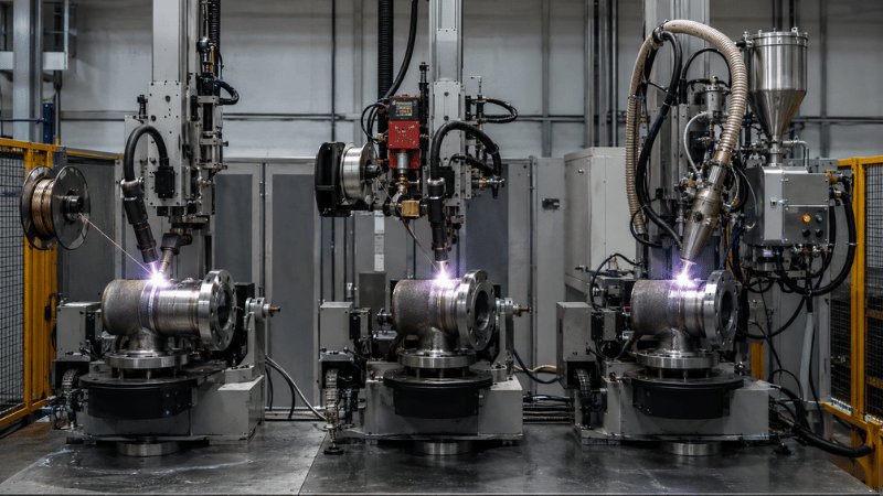
Manufacturers evaluating this route can review the iKratz Hot Wire Surfacing Welding System, designed for automated TIG overlay on pipes, valves, fittings, and corrosion- or wear-resistant components.
Hot-wire TIG is not automatically faster on every part. Restricted bores, frequent starts, short beads, unstable wire positioning, and long loading times can erase the theoretical advantage.
The honest comparison is therefore not maximum deposition rate. It is accepted overlay produced per shift, including setup, interpass waiting, inspection, and rework.
PTA vs TIG Cladding
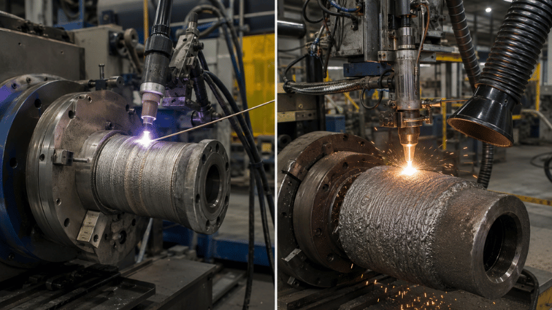
The PTA cladding process uses a transferred plasma arc and normally introduces alloy powder into a concentrated heat source. TIG typically uses wire, while PTA gives manufacturers access to a broad range of powder chemistries.
PTA is widely associated with wear-resistant deposits, cobalt-based alloys, nickel-based hardfacing materials, valve seats, drilling components, agricultural tooling, and parts requiring thicker functional layers.
TIG is generally favored for controlled corrosion-resistant overlays, smooth beads, restricted geometries, and applications where deposited chemistry must be managed carefully.
Technical Performance Comparison
Cold-Wire TIG vs Hot-Wire TIG vs PTA
Productivity, dilution, access, and investment at a glance.
| Factor | Cold-Wire TIG | Hot-Wire TIG | PTA |
|---|---|---|---|
| Feedstock | Wire | Preheated wire | Powder |
| Productivity | Low to moderate | Moderate to high | High |
| Dilution control | Excellent | Excellent when optimized | Good, process-dependent |
| Surface finish | Excellent | Excellent | Moderate to good |
| Thick deposits | Less efficient | More efficient | Very suitable |
| Alloy flexibility | Limited by wire availability | Limited by wire availability | Broad powder selection |
| Tight-access capability | Strong | Geometry-dependent | More restricted |
| Post-machining | Often limited | Often limited | Frequently required |
| Capital complexity | Lower | Medium to high | High |
PTA should not be described as universally faster or more diluted than TIG. Actual performance depends on powder flow, arc energy, travel speed, deposit thickness, bead overlap, substrate condition, and operator or automation stability.
Similarly, a low-dilution laboratory coupon does not prove that the process will maintain the same result inside a deep valve bore after several hours of production.
Dilution Can Change the Winning Process
Weld overlay dilution is the percentage of base metal mixed into the deposited alloy. Some substrate melting is necessary for fusion, but excessive mixing can reduce chromium, nickel, molybdenum, or other critical alloying elements at the finished surface.
This is why the fastest single-layer deposit may not produce the lowest-cost component. If excessive iron pickup forces a second layer, the project consumes more filler, gas, machine time, and machining allowance.
For practical background on how base-metal mixing changes weld chemistry, see the iKratz guide to welding stainless steel to carbon steel.
A reliable comparison should test dilution through representative macro sections and deposited-metal chemistry. Measuring heat input alone is not enough because different combinations of current and travel speed can produce similar calculated heat input but different penetration profiles.
The goal is not simply “low dilution.” It is sufficient fusion combined with chemistry that meets the application requirement after final machining.
Compare Total Cost per Accepted Component
Equipment price is only the visible part of cladding cost. The quieter expenses are often more dangerous because they arrive disguised as normal production.
Capital cost may include the welding power source, hot-wire supply, powder feeder, manipulator, robot, positioner, extraction, cooling, cameras, seam tracking, and parameter-recording system.
Operating cost includes filler material, powder loss, shielding gas, electrodes, nozzles, labor, maintenance, cleaning, and preventive replacement of feeding components.
Then come hidden costs: setup time, preheating, interpass delays, rejected layers, chemistry failures, machining, inspection, qualification, and downtime during product changeover.
A useful formula is:
Cost per accepted component = total production and quality cost ÷ accepted components
This calculation prevents a high deposition rate from hiding poor yield. A process depositing four kilograms per hour is not impressive when half a kilogram must be machined away and the first part fails chemistry testing.
A Practical Process-Selection Framework
Begin by defining the overlay objective. Corrosion protection, abrasive wear resistance, impact resistance, dimensional restoration, and high-temperature service require different alloy and process priorities.
Next, score the actual component. Record base material, overlay alloy, finished thickness, maximum dilution, bore depth, minimum diameter, annual volume, batch size, surface requirement, and machining allowance.
Cold-wire TIG usually reaches the shortlist when maximum control and geometry flexibility matter most. Hot-wire TIG fits repeated production requiring a balance of TIG quality and improved productivity. PTA becomes compelling for powder-alloy flexibility, hardfacing, and thicker deposits.
Do not make the final decision from datasheets. Run representative trials using the intended alloy, substrate, geometry, orientation, and layer strategy.
The validation plan should include macro sections, overlay thickness, fusion checks, chemistry analysis, dilution measurement, hardness testing, and corrosion or wear testing where relevant.
For pressure-related work, welding procedures and personnel may need qualification under ASME BPVC Section IX. A successful demonstration bead is useful evidence, but it is not automatically a qualified production procedure.

Automation and Production Reality
Mechanized systems control motion while an operator supervises the process. Fully automatic systems execute programmed sequences with less intervention. Robotic cells add flexible multi-axis positioning for changing geometries.
Useful automation features include synchronized wire feeding, torch oscillation, arc-voltage control, programmable overlap, automatic layer stepping, recipe storage, camera monitoring, alarms, and parameter logging.
However, automation repeats poor setup just as faithfully as good setup. Component runout, weak fixtures, incorrect wire angle, contaminated feedstock, or inconsistent datum positions can produce highly repeatable defects. Very efficient, technically speaking—just not in the direction anyone wanted.
When comparing suppliers, request total cycle time rather than arc-on time. Loading, alignment, preheating, interpass cooling, inspection, cleaning, and unloading belong in the calculation.
Also ask whether a factory acceptance test will use a representative component. Watching an empty positioner rotate proves the motor works. It does not prove the system can produce your overlay.
Common Cladding Problems
Excessive dilution usually requires a coordinated review of arc energy, travel speed, wire or powder input, torch position, bead overlap, and layer thickness. Simply reducing current may create incomplete fusion.
Poor bead shape can come from unstable wire placement, incorrect torch angle, inconsistent powder flow, component runout, or badly tuned oscillation.
Cracking requires evaluation of alloy compatibility, substrate condition, preheat, interpass temperature, residual stress, and post-weld heat treatment. It should never be treated as a cosmetic inconvenience.
Inconsistent deposition often points to feeding or positioning problems rather than the nominal welding procedure. Record setup dimensions so production does not depend on an operator remembering where the wire “looked about right.”
Welding also introduces fumes, ultraviolet radiation, hot surfaces, electrical hazards, and fire risks. PTA adds powder-handling and extraction concerns. OSHA’s welding, cutting, and brazing safety guidance provides an authoritative overview of the hazards and control measures.
Frequently Asked Questions
Is hot-wire TIG always faster than cold-wire TIG?
Hot-wire TIG generally offers higher filler-melting efficiency, but actual output depends on alloy, geometry, wire access, heat limits, starts and stops, and total handling time.
Does PTA cladding always create more dilution than TIG?
No. Dilution depends on arc energy, travel speed, deposit thickness, powder flow, equipment setup, and substrate conditions. Representative testing is required.
Which process is best for corrosion-resistant overlay?
TIG is often preferred for controlled stainless-steel or nickel-alloy overlays. However, chemistry limits, geometry, layer count, production volume, and machining requirements determine the final choice.
Can one automated system perform every cladding job?
Rarely. ID and OD access, component weight, bore dimensions, feedstock type, orientation, alloy behavior, and inspection requirements usually demand application-specific tooling or machine configurations.
Conclusion: Which Cladding Process Should You Choose?
In hot-wire TIG vs cold-wire TIG, cold wire wins when control, access, lower complexity, and repair flexibility dominate. Hot wire wins when repeat production needs higher filler-melting efficiency without giving up TIG’s controlled pool and smooth finish.
In PTA vs TIG cladding, PTA is often stronger for powder-based hardfacing and thicker deposits, while TIG suits controlled corrosion-resistant overlays and demanding geometry. The final decision should come from representative trials and total cost per accepted component, not brochure deposition rates.
Build the Right Cladding System
iKratz develops automated TIG and hot-wire overlay systems around your component geometry, base material, filler alloy, cladding position, inspection requirements, and production target. This application-led approach helps reduce access conflicts, unstable wire feeding, unnecessary machine features, and expensive qualification surprises.
Share your drawings, materials, target thickness, and annual output with our engineering team. Contact us today to request an application review, technical recommendation, and representative weld-trial plan.