
Distortion in welding is one of the most common problems in metal fabrication. It happens when metal heats and cools unevenly, causing unwanted movement in the workpiece. This can occur during welding or thermal cutting, and it often affects far more than appearance.
Even minor distortion can lead to poor fit-up, dimensional error, rework, slower assembly, and higher labor cost. This guide explains the main welding distortion causes, why the aluminum welding process needs extra attention, and practical ways to control distortion in both welding and cutting.
What Is Distortion in Welding?
Distortion in welding is the unwanted shape change caused by uneven thermal expansion and contraction. When one area of the workpiece expands or contracts more than another, the metal may bend, twist, bow, or shrink out of tolerance.
This is closely linked to residual stress. When heated metal is restrained and cannot move freely, internal stress builds up. After cooling, some stress remains locked inside the part, while some appears as visible distortion. Residual stress stays in the material, while distortion shows up in the final shape.
From a fabrication perspective, distortion is the visible result of unbalanced thermal movement. That is why controlling it requires attention not only to the weld itself, but also to joint design, restraint, sequence, and heat input.
Common Types of Distortion in Welding
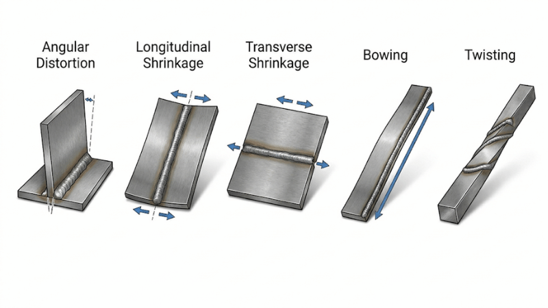
Angular distortion happens when one side of a joint shrinks more than the other, changing the final angle of the part. This is common in fillet and groove welds.
Longitudinal shrinkage pulls along the weld length, while transverse shrinkage pulls across the weld width. These effects can shorten a component, affect alignment, or create fit-up problems during assembly.
Thin materials may also experience bowing, buckling, and twisting. Bowing creates a gradual curve, buckling causes waviness, and twisting produces rotational movement. Large panels and light structures are more vulnerable because they have less stiffness.
Different distortion types do not respond to the same fix. One job may need a better weld sequence, while another may need reduced weld size, stronger fixturing, or a different joint design.
What Causes Distortion in Welding?
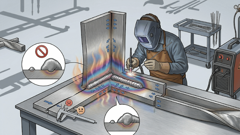
The most common cause is excessive heat input. More heat means more expansion during welding and more contraction during cooling, which increases the chance of movement.
Another major cause is large weld size or excess weld metal. Overwelding adds unnecessary shrinkage force, more filler, and more heat than the joint requires. It is one of the most common and avoidable reasons for distortion.
Poor joint design and fit-up also make control harder. Wide gaps, poor edge preparation, and unbalanced joints increase weld volume and reduce consistency. If the joint is badly prepared, distortion risk rises before welding even starts.
Incorrect welding sequence can pull the part unevenly, while weak support allows the structure to move too freely. Thin sections, large unsupported areas, and open-frame fabrications are especially sensitive. In most cases, distortion comes from several process decisions working against each other.
Why the Aluminum Welding Process Needs Special Attention
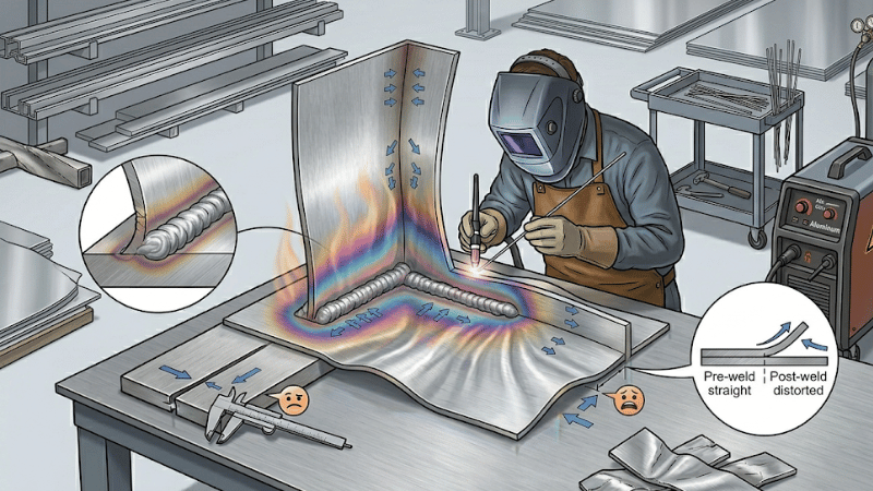
The aluminum welding process requires tighter control because aluminum reacts to heat differently from steel. It spreads heat quickly and moves more during temperature change, which makes distortion harder to manage.
That is why aluminum welding distortion is often more noticeable in sheet metal, panels, housings, and lightweight structures. Even when the weld itself is sound, the surrounding material may still move enough to affect fit-up and dimensional accuracy.
Aluminum also leaves less room for sloppy habits. Poor fit-up, unnecessary dwell time, excessive passes, or overwelding can create distortion quickly. A welding approach that works on steel may fail on aluminum if process control is not tightened.
Distortion Risks in the Aluminum Welding Process
One major risk in the aluminum welding process is that heat does not stay localized easily. It spreads through the workpiece quickly, enlarging the affected area and increasing movement outside the weld zone.
Thin aluminum sections are especially easy to warp. The lighter and thinner the structure, the easier it is for heat to shift the shape of the part. This is why aluminum work often demands more careful sequencing and restraint.
Poor joint preparation increases the risk further. Bad fit-up, contamination, and unnecessary gaps usually require more arc time and filler metal. That means more heat, more shrinkage, and more distortion.
Overwelding is especially costly on aluminum. Extra weld metal creates more shrinkage force, while extra passes bring repeated heating cycles. Sequencing mistakes can then amplify movement across the assembly.
Methods of Controlling Distortion in Welding
The first rule of welding distortion control is to use only as much weld metal as necessary. Correct weld sizing reduces shrinkage force, and intermittent welds can help where design allows.
Proper joint design is another major factor. Better groove choice, balanced geometry, and tighter fit-up reduce weld volume and help shrinkage act more evenly. This clearly shows why distortion prevention starts before the arc is struck.
Controlling heat input is equally important. The goal is to use enough heat to make a sound weld, but not more than necessary. Travel speed, arc time, process choice, and pass count all affect the thermal load placed on the part.
Balanced welding techniques also help. Welding from both sides can reduce angular pull. Backstep welding and skip welding help spread heat and shrinkage instead of concentrating them in one area.
Clamps, jigs, and fixtures are useful, but they need to be applied intelligently. Too little restraint allows excessive movement, while too much restraint can trap stress that appears later after release.
Fabricators may also preset or prebend parts to offset expected shrinkage. On repeat work, this can be an efficient way to compensate for predictable movement. Most importantly, weld sequence should be planned around geometry, symmetry, stiffness, and support conditions.
Best Practices for Controlling Distortion in Aluminum Welding
For aluminum, process selection directly affects heat distribution and dimensional stability. Choosing a process that limits unnecessary thermal load can make distortion easier to control from the start.
Heat discipline matters even more on aluminum than on steel. Unnecessary dwell time, too many passes, inconsistent travel speed, and weak fit-up control can quickly lead to warping.
Fixturing should support the part without over-restraining it. Too little support allows movement during welding, while too much restraint can lock in stress that appears after unclamping or during later operations.
It is also important to balance productivity with accuracy. Faster output is not helpful if it creates rework, scrap, or assembly problems. In some cases, adjusting the joint design or increasing stiffness is more effective than changing the welding procedure alone.
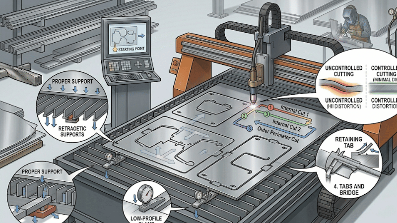
Methods of Controlling Distortion When Making Cuts
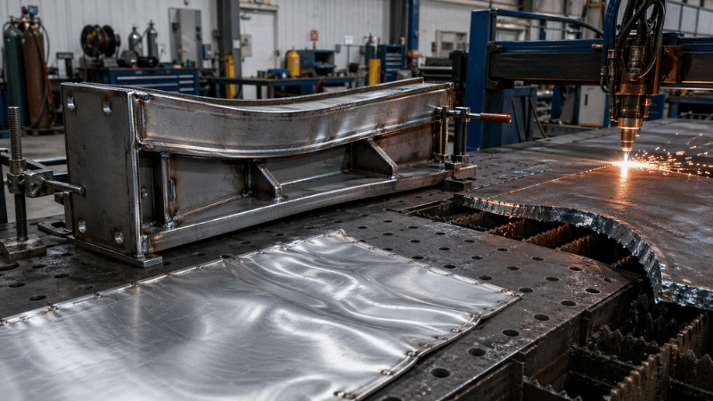
Distortion is not only a welding issue. Methods of controlling distortion when making cuts matter because thermal cutting also introduces localized heat, followed by cooling shrinkage and shape change.
This means cutting distortion control starts with process choice, cut sequence, and heat distribution. If too much heat is concentrated in one area, large plates and thin sections may warp before welding even begins.
Balanced cutting patterns and staged cutting help spread heat more evenly across the workpiece. Proper support and restraint are also important, especially for thin materials that may sag, lift, or shift during cutting.
Leaving tabs, bridges, or planned supports can improve stability until the cut is complete. Better cutting discipline often prevents distortion problems that might otherwise be blamed on welding later.
Welding Distortion vs Cutting Distortion
Welding distortion and cutting distortion share the same root cause: uneven thermal expansion and contraction. Both can reduce dimensional accuracy, create fit-up problems, and increase rework. Both also benefit from planning, sequencing, and proper restraint.
The difference is in how the heat acts on the part. Welding adds filler metal and creates joint shrinkage, while cutting removes material and introduces heat along the cut path. Because of that, the control methods overlap, but the process decisions are not identical.
That is why welding sequence and cutting sequence should usually be planned separately, especially in jobs involving thin materials, large plates, or tight tolerances.
A Practical Distortion Control Checklist
Before production starts, review material type, thickness, and part geometry. Thin materials, large unsupported sections, and lightweight structures usually carry higher distortion risk.
Next, check joint design and fit-up. Reducing unnecessary weld volume is one of the most effective ways to prevent movement later in the process.
Set the welding sequence in advance, and plan cutting order separately. Confirm restraint and fixturing strategy, including clamp points, support locations, and expected movement during heating.
Finally, inspect early. Distortion is usually easier and cheaper to correct during intermediate stages than after the full assembly is complete.
Common Mistakes That Increase Distortion
Using more heat than necessary remains one of the most common mistakes. It increases expansion, contraction, and movement in both welding and cutting.
Another frequent error is choosing weld size by habit instead of design requirement. Oversized welds waste filler metal, increase shrinkage force, and create avoidable distortion.
A particularly costly mistake is treating aluminum like steel. Aluminum requires different process discipline, especially in heat control, fit-up, and sequence planning.
Shops also often ignore cut sequence in thermal fabrication. A poor cutting order can distort a part before welding even starts. When distortion is corrected too late in the process, the repair becomes slower and more expensive.
FAQs
What is the main cause of distortion in welding?
The main cause is uneven heating and cooling, which creates unbalanced expansion and contraction in the workpiece. Excessive heat input and overwelding make the problem worse.
Why is aluminum more likely to warp during welding?
Aluminum spreads heat quickly and moves more during temperature change, especially in thin sections. That makes it more sensitive to thermal distortion if process control is not tight.
Can cutting operations cause distortion too?
Yes. Thermal cutting introduces localized heat, which can cause movement, warping, and dimensional change during cooling, especially in thin materials and large plates.
What is the best way to reduce welding distortion?
The most effective approach usually combines correct weld sizing, sound joint design, controlled heat input, smart sequence planning, and balanced fixturing.
Conclusion
Distortion in welding is not random or unavoidable. It can be reduced through better planning, sound joint design, smarter sequencing, balanced restraint, and controlled heat input. Shops that treat distortion as a process variable instead of a surprise problem usually achieve better fit-up, less rework, and lower production cost.
The aluminum welding process requires even more deliberate control because aluminum spreads heat quickly and moves more during thermal cycling. Since cutting can introduce distortion before welding starts, both operations should be addressed together in fabrication planning.
Want Better Dimensional Control From the Start?
If your project involves aluminum fabrication, thermal cutting, or tight-tolerance welded assemblies, distortion control should be part of the process plan from day one. The right manufacturing partner helps reduce rework, improve fit-up quality, and support more consistent production results.
Contact us today to discuss your fabrication requirements. We can help you choose welding and cutting strategies that improve dimensional stability and reduce unnecessary correction.