Semiconductor gas lines have no room for “close enough.” One contaminated weld can introduce particles, moisture, oxidation, or leaks into an ultra-high-purity system.
That is why orbital welding for semiconductor applications requires more than automated TIG equipment. It combines controlled preparation, stable purging, qualified parameters, inspection, and full traceability.
What Is Semiconductor Orbital Welding?
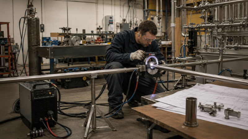
Orbital welding is a mechanized GTAW process in which the tube remains stationary while the electrode rotates around the joint. Current, pulse timing, travel speed, shielding gas, and cooling are controlled by a programmable system.
The basic process is explained in TWI’s orbital welding guide. Semiconductor applications, however, require much stricter cleanliness, internal weld quality, and documentation than general stainless-steel welding.
Manual TIG depends heavily on the welder’s torch angle, arc length, and travel speed. Orbital welding reduces these variables by repeating an approved cycle.
It does not make welding foolproof. It makes the process repeatable and measurable, which is far more valuable.
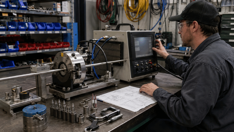
Why UHP Gas Lines Need Specialized Weld Control
Semiconductor UHP systems may carry inert, corrosive, toxic, reactive, or pyrophoric gases. Their internal surfaces must remain clean, smooth, leak-tight, and free from defects that could trap contaminants.
Common contamination risks include particles, hydrocarbons, moisture, and oxidation. Weld-integrity risks include porosity, incomplete penetration, excessive penetration, and tube misalignment.
A rejected weld can cause rework, additional testing, delayed commissioning, and cleanroom disruption. The price of the fitting is usually the smallest part of the headache.
Standards such as SEMI F81 provide semiconductor-specific inspection guidance. Approved project specifications and qualified procedures should always take priority.
Materials and Clean Handling
Electropolished 316L stainless-steel tubing is widely used in UHP gas line welding because of its corrosion resistance, weldability, and controlled internal finish.
Before production, verify material certificates, heat numbers, tube dimensions, wall thickness, and surface-finish requirements. Parameters qualified for one wall thickness should not be casually reused for another.
Tubing and fittings should remain capped until controlled assembly. Keep cut ends away from carbon-steel tools, dirty benches, oily gloves, and grinding debris.
In high-purity work, storage and handling are part of the welding process. Contamination does not care which department caused it.
How to Select an Orbital Tube Welding Machine
Start with the application: tube diameter, wall thickness, material, joint type, gas service, weld volume, workspace, and documentation requirements.
The power supply should provide programmable current, pulsing, rotation, gas timing, weld-program storage, and parameter security. Approved settings should not be “improved” midway through production by an enthusiastic operator.
For compact semiconductor tubing, an enclosed head is often preferred because it surrounds the joint with a shielding chamber. The MWF-12 mini closed orbital welding head is suited to small-diameter tubing and restricted access.
Also evaluate calibration support, weld-data recording, collet availability, operator training, spare parts, cooling, and procedure-development assistance.
A practical equipment scorecard should cover:
- Tube-size compatibility
- Physical access
- Parameter control
- Weld traceability
- Calibration support
- Purge integration
- Training
- Cleanroom suitability
The best orbital tube welding machine is not necessarily the most powerful one. It is the machine that fits the joint, the workspace, and the quality system.
Enclosed vs. Open Orbital Weld Heads
Enclosed weld heads clamp around the joint and create a controlled shielding chamber. They are commonly used for thin-wall tube-to-tube and tube-to-fitting welds.
Their strengths include compact access, stable shielding, and repeatability. Their weakness is a low tolerance for poor facing, incorrect alignment, or excessive joint gaps.
Open weld heads provide better visibility and suit larger diameters, thicker walls, unusual joint geometry, or filler-wire applications. However, shielding is more exposed to drafts and setup variation.
For small-diameter high-purity orbital welding, enclosed heads are often the first choice. Open heads are more suitable when component size or joint design exceeds enclosed-head capability.
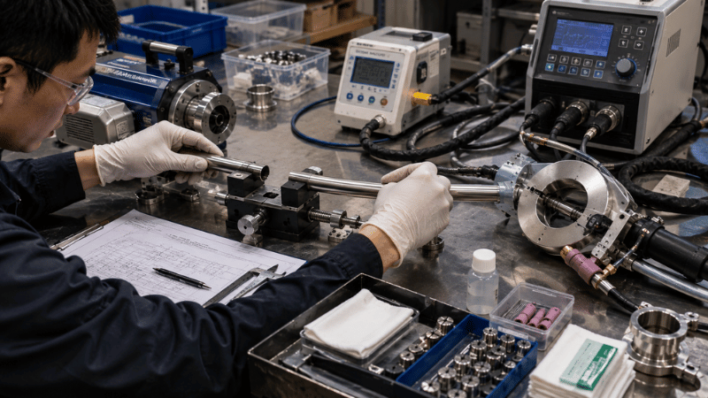
High-Purity Orbital Welding Workflow
Begin by confirming drawings, material specifications, heat numbers, tube dimensions, welding procedures, machine calibration, and operator authorization.
Cut and face the tube squarely using suitable tooling. Remove burrs, chips, oil, fingerprints, and cleaning residue using the approved method.
Next, align the joint. Tube ends should be concentric, correctly seated in the collets, and assembled with the qualified gap condition.
Poor facing cannot be repaired by adding more current. That only creates a hotter problem.
Inspect the tungsten electrode for correct type, diameter, grind geometry, extension, and cleanliness. A damaged or contaminated electrode can affect arc stability and penetration.
Establish shielding and internal purge using the required gas purity, flow, and duration. Measuring residual oxygen is more reliable than relying only on purge time.
Finally, load and verify the approved weld program. Confirm material, wall thickness, current, pulse timing, rotation speed, and gas settings before starting the cycle.
After welding, allow the complete post-flow period, inspect the joint, assign its weld number, and record the result.
From Collision and Oxidation to 100% Qualification
Head Collision
Over 38 mm clearance could not fit the 32 mm valve gap.
Weld Oxidation
Air leakage caused heat tint and failed the oxygen limit.
💸 Financial Toll
⚙️ The iKratz Fix
22 mm Clearance
Completed 360° welds without collision.
Gas-Tight Seal
Blocked air ingress and heat tint.
Oxygen Interlock
Locked the arc above 5 ppm.
Purge Gas and Oxygen Control
Internal purging protects the root side of the weld from oxidation. Poor purge control can create discoloration, rough internal surfaces, and oxide particles.
More flow is not always better. Excessive purge pressure can disturb the molten root or cause concavity.
Control gas purity, flow rate, purge duration, outlet restriction, tube volume, and residual oxygen. A clean external bead does not prove that the internal weld is acceptable.
Argon and other inert gases can displace breathable air. Follow OSHA compressed-gas guidance, especially in enclosed or poorly ventilated areas.
Procedure Qualification and Production Readiness
A saved machine program is not the same as a qualified welding procedure.
The program proves only that the controller remembers its settings. Qualification proves that those settings produce an acceptable weld under defined conditions.
Representative coupons should match the actual material, tube diameter, wall thickness, preparation method, weld head, purge arrangement, and inspection requirements.
Operators must also demonstrate competence with the specific system and procedure. Knowing where the Start button is located is useful, but it is not a qualification.
Before production, verify:
- Approved welding procedure
- Accepted weld coupons
- Calibrated equipment
- Qualified operator
- Verified materials
Without these controls, semiconductor pipe welding becomes an expensive trial-and-error exercise.
Inspection and Weld Traceability
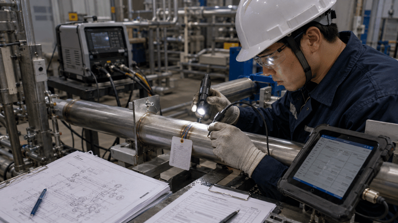
Visual inspection should examine bead consistency, alignment, discoloration, arc-start condition, penetration, root appearance, and oxidation.
Leak testing must follow the project-approved method, calibrated instruments, and specified acceptance criteria. Avoid universal claims because requirements vary by gas service, owner, and system classification.
Each weld should be linked to its drawing location, weld number, operator, machine, program, material heat, date, and inspection status.
A turnover package may include material certificates, calibration records, procedures, operator qualifications, weld maps, machine logs, inspection reports, and leak-test results.
Traceability may feel excessive—right up until someone asks why a weld failed.
Common Weld Defects and Corrective Actions
Oxidation usually indicates poor purging, oxygen ingress, insufficient shielding, or interrupted post-flow. Check gas purity, hose connections, seals, and residual oxygen.
Incomplete penetration may result from low heat input, incorrect dimensions, poor fit-up, fast rotation, or the wrong program.
Excessive penetration often points to high current, slow rotation, thin material, or excessive internal pressure.
Porosity commonly comes from moisture, contamination, dirty tube ends, unstable shielding, or gas leaks.
Misalignment is usually caused by poor facing, incorrect collets, worn tooling, or careless loading.
When defects repeat, stop production. Quarantine affected welds, confirm the program, inspect the electrode and tooling, check calibration and purge performance, and produce another coupon.
The machine often gets blamed first because it cannot argue back. In reality, preparation, tooling, purging, and program selection are frequent root causes.
Buy, Rent, or Outsource?
Buying makes sense for recurring work, high weld volume, and teams that can maintain qualified procedures, calibrated equipment, and trained operators.
Renting is useful for temporary projects or short-term capacity shortages. Confirm that the package includes the correct head, collets, cables, cooling system, consumables, calibration records, and technical support.
Outsourcing may be the safer choice when semiconductor experience, documentation, qualification, or schedule risk exceeds internal capability.
Base the decision on project duration, tube-size range, weld volume, internal expertise, documentation workload, downtime risk, and equipment utilization.
For broader equipment guidance, visit iKratz or explore its semiconductor UHP gas-system solutions.
Conclusion
Successful orbital welding for semiconductor systems depends on more than the welding machine. Tube preparation, alignment, electrode condition, purging, qualified parameters, inspection, and documentation must work as one controlled process.
Choose equipment according to tube dimensions, access, traceability, production volume, and project risk. The real objective is not simply a neat external bead. It is a clean, repeatable, inspectable, and fully documented UHP weld.
Build a More Reliable UHP Welding Process
iKratz helps semiconductor contractors, fabricators, and facility teams match orbital welding equipment to tube sizes, access restrictions, production targets, and documentation requirements. Our application-focused support helps customers improve setup consistency, weld control, operator efficiency, and project readiness.
Share your tube dimensions, material, weld volume, and documentation needs with our team. Contact us today for a technical recommendation or quotation.
Frequently Asked Questions
Why is orbital welding used for semiconductor gas lines?
It provides repeatable movement, controlled heat input, stable shielding, and programmable weld cycles. When supported by qualified procedures and correct preparation, it helps produce consistent and traceable UHP welds.
What makes high-purity orbital welding different?
High-purity welding requires stricter control of cleanliness, purge gas, residual oxygen, internal surface condition, material traceability, inspection, and documentation.
Is an enclosed weld head always the best option?
No. Enclosed heads suit compact, thin-wall, autogenous tubing. Open heads may be better for larger diameters, thicker walls, restricted joint geometry, or filler-wire welding.
How important is oxygen monitoring during purging?
It is highly valuable because purge time alone does not confirm internal conditions. Tube volume, leaks, restrictions, and outlet design can all affect residual oxygen.
Should we buy an orbital welder or hire a contractor?
Buy for recurring, high-utilization work with qualified internal staff. Rent for temporary needs. Outsource when expertise, qualification, documentation, or schedule risk cannot be managed confidently in-house.