
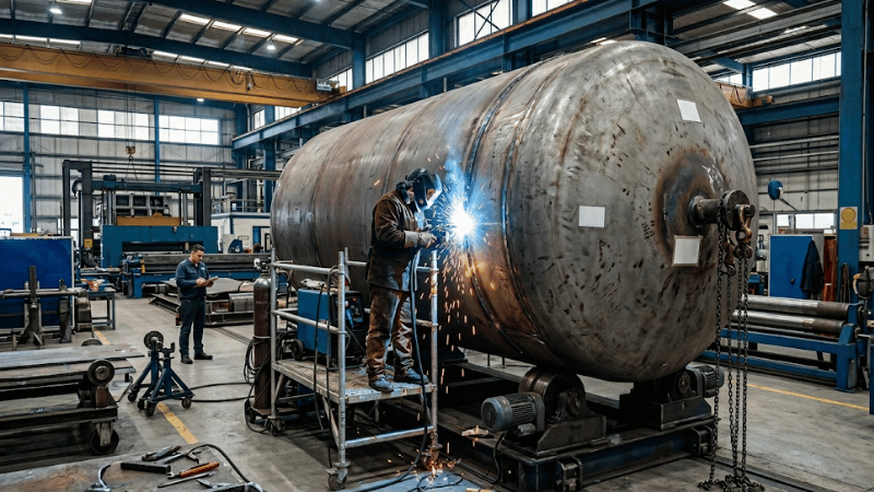
Pressure vessel welding is not ordinary fabrication. These welds must hold pressure, pass inspection, and perform safely in service.
This guide covers the main pressure vessel welding methods, why SAW remains central, where Narrow Gap SAW improves cost control, and how code and NDT affect quality.
Talk to an Engineer About Your Welding Requirements
Need help reviewing vessel drawings, material specs, or welding options? A capable fabricator should be able to assess process choice, inspection requirements, and production risk before fabrication starts.
What Makes Pressure Vessel Welding Different?
Pressure vessel welding has a higher bar than general welding because the weld becomes part of the pressure boundary. Material traceability, qualified procedures, inspection, testing, and documentation all matter.
The consequences are different too. A poor weld on general steelwork may mean rework. A poor weld on a vessel can mean leaks, failed inspection, delays, or service risk. That is why vessel welding is treated as controlled manufacturing, not just welding execution.
How Pressure Vessel Manufacturing and Welding Connect
In pressure vessel manufacturing, welding is only one part of the system. Material selection, forming, rolling, fit-up, and bevel prep all affect final weld quality. Even a qualified procedure cannot fix poor joint preparation.
Production usually moves through shell seams, circumferential seams, head welds, and nozzle attachments. After welding, inspection, NDT, possible PWHT, pressure testing, and records complete the job. Buyers should ask not only what process is used, but how welding fits into the supplier’s full quality-control system.
Main Pressure Vessel Welding Processes and When They’re Used
Pressure vessel welding processes are selected by joint type, material, thickness, access, and production efficiency. Most projects use more than one process.
Process Selector: Efficiency & Metallurgical Goals
Quantifiable Benchmarks for ASME Section VIII Fabrication
| Process | Deposition Rate | Primary Strength | ikratz “Real-World” Metric |
|---|---|---|---|
| SAW (Sub-Arc) | 10 – 25 kg/h | Zero-spatter; Deep penetration for heavy shell seams. | Mandatory for shell seams > 38mm. 35% filler saving with Narrow Gap prep. |
| GTAW (TIG) | 1 – 3 kg/h | Ultimate root pass integrity; Class-1 X-ray quality. | Required for high-purity or stainless root passes to ensure zero internal concavity. |
| GMAW (MIG) | 4 – 8 kg/h | High versatility; pulsed spray for clean stainless work. | Ideal for nozzle-to-shell attachments. 40% faster than SMAW in shop air. |
| FCAW (Flux-Core) | 5 – 9 kg/h | Deep fusion in out-of-position welds (vertical/overhead). | Best for thick external attachments. High slag protection for slower cooling. |
| SMAW (Stick) | 1.5 – 3.5 kg/h | Independent of shielding gas; critical for field repairs. | Specify E7018-H4R for hydrogen control in $CE > 0.45$ carbon steels. |
“Engineering Insight: In our 80mm pipeline case study, switching from standard V-bevel SMAW/GMAW to Narrow Gap SAW reduced total arc-time by 6-7 minutes per layer while refining HAZ grain structure to Level 7.”
SAW is widely used for long shell seams and controlled shop production. GTAW is preferred where root quality matters, while SMAW, GMAW, and FCAW are often used where geometry, access, or workflow make them more practical.
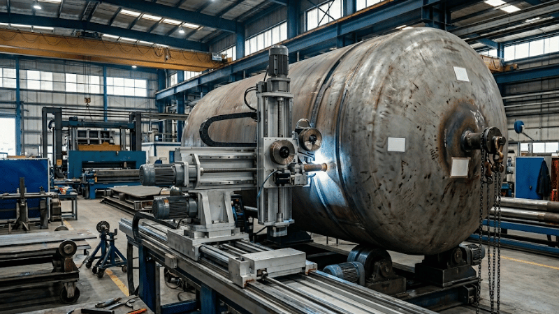
Why SAW Still Matters—and Why Narrow Gap SAW Matters More
SAW pressure vessel welding remains a core choice for long seams because it combines productivity with repeatability. But in thick-wall vessel fabrication, simply saying “we use SAW” is no longer enough.
The more useful question is whether the shop can handle Narrow Gap SAW. Narrow-gap design reduces weld volume, filler consumption, pass count, and total heat input. For thick sections, that usually means lower cost, less distortion, and fewer repair opportunities.
In short, Narrow Gap SAW is not just a welding detail. It is a practical manufacturing advantage.
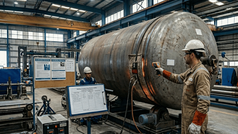
Code Compliance: What Buyers and Engineers Need to Know
ASME pressure vessel welding is about more than a weld looking sound. Code-sensitive fabrication depends on procedure qualification, welder qualification, inspection planning, traceability, and documentation.
A WPS defines how welding should be performed. A PQR supports the procedure with qualification data. Welder qualification confirms the operator is approved for the required variables. Together, these records show whether the shop runs a controlled process.
Traceability and PWHT planning matter too. A supplier should be able to explain how materials, filler metals, procedures, and inspection records stay linked throughout fabrication.
The Biggest Quality Risks in Pressure Vessel Welding
Pressure vessel welding quality control is not just about finding defects after welding. Problems such as lack of fusion, incomplete penetration, porosity, slag inclusion, and cracking can lead to repairs, failed inspection, and schedule overruns.
For plate-built vessels, hydrogen-assisted cold cracking is one of the biggest risks, especially in thick sections and restrained joints. That is where Carbon Equivalent (CE) becomes useful. A common IIW formula is: CE = C + Mn/6 + (Cr + Mo + V)/5 + (Ni + Cu)/15.
When CE approaches or exceeds 0.45, weldability concerns usually increase, especially when thickness, restraint, or hydrogen control are unfavorable. In real fabrication, that often means preheat stops being a shop preference and becomes a WPS-controlled requirement.
The heat-affected zone also matters. In thicker sections, thermal cycles can affect hardness, toughness, and residual stress. Good quality control is not only about detecting defects, but reducing the conditions that create them.
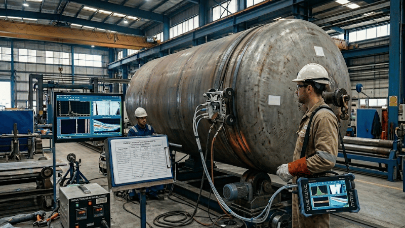
Inspection and NDT Methods Used for Pressure Vessel Welds
Pressure vessel weld inspection should match the weld geometry, material, and defect risk. RT and UT remain common, but many manufacturers now treat PAUT and TOFD as upgrades rather than extras.
That shift matters because vessel risk is not only about volumetric flaws. Planar defects such as lack of fusion, cracks, and incomplete penetration are often more critical. In these cases, PAUT/TOFD can offer better characterization, digital records, and no radiation exclusion zone.
RT still has value, but for many weld-quality strategies, PAUT and TOFD represent the more modern inspection path.
NDT Decision Matrix: Detection Sensitivity & Efficiency
Comparing RT, PAUT, and TOFD for ASME Section VIII Compliance
| Method | Target Defect | Detection Rate (Planar) | Inspection Speed | ikratz Field Metric |
|---|---|---|---|---|
| RT (Radiography) | Volumetric (Porosity, Slag) | ~ 65% | Slow (8h+ incl. Dev) | Standard for wall thickness < 25mm. High radiation exclusion risk. |
| PAUT (Phased Array) | Planar (LOF, Cracks) | > 92% | Fast (1.5h Real-time) | Best for thick-wall Longitudinal seams. 30% higher LOF detection than RT. |
| TOFD (Diffraction) | Sizing (Crack Depth) | Superior Accuracy | Moderate | Accurate sizing within ± 1mm. Essential for Life-Cycle Assessment (LCA). |
| MT / PT (Surface) | Surface Cracks / Pinholes | Surface Only | Fast | Mandatory for final verification of Nozzle-to-Shell attachments. |
ikratz Engineering Tip: Why We Advocate PAUT over RT
In a recent audit of an 80mm shell seam, RT failed to identify a sidewall Lack of Fusion (LOF) due to grain scattering and beam orientation. PAUT, using multi-angle focal laws, successfully identified the defect with a 92% confidence level. Furthermore, switching from RT to PAUT on a 4-meter circumferential seam reduced the inspection cycle from 8 hours (including film processing) to just 90 minutes, allowing simultaneous shop activity.
How to Choose the Right Welding Method
The best pressure vessel welding method balances quality, compliance, inspectability, and efficiency. Stainless and alloy applications may need cleaner root processes, while thick carbon steel seams often benefit from high-deposition methods.
Wall thickness, joint access, and production volume also matter. Manual methods suit one-off or variable work, while mechanized approaches work better for repeatable seams. A fast process is not efficient if it creates distortion, repair, or inspection trouble later.
Manual vs. Mechanized vs. Automated Welding
Manual welding still matters in pressure vessel fabrication, especially for repairs, low-volume work, and restricted-access joints.
Mechanized and automated welding are strongest where joints are consistent and setup is controlled. Their biggest advantage is reduced variation, which helps stabilize heat input, bead quality, and inspection outcomes.
A good supplier should explain where automation improves results and where manual expertise is still the better choice.
How to Evaluate a Pressure Vessel Fabricator
A reliable pressure vessel fabricator should clearly explain welding processes, qualified thickness ranges, WPS/PQR control, NDT coordination, traceability, and PWHT planning.
Project-specific experience matters as well. A supplier strong in thick-wall carbon steel shells may not be equally strong in stainless, nozzle-heavy fabrication. Warning signs include vague answers, weak inspection logic, or too much talk about “experienced welders” without clear process control.
Pressure Welding vs. Pressure Vessel Welding
“Pressure welding” is a broad term for joining methods that use pressure in the joining process. Pressure vessel welding is different. It refers specifically to fabricating pressure-retaining equipment under code, inspection, and manufacturing-control requirements.
That distinction matters because buyers are looking for fabrication capability, not generic welding theory.
FAQs
What welding process is most commonly used for pressure vessels?
SAW is commonly used for long shell seams and thicker sections, while GTAW is often used for root passes or precision work. SMAW, GMAW, and FCAW may also be used depending on access, material, and production requirements.
Why is Narrow Gap SAW important in thick-wall vessel fabrication?
Because it can reduce weld volume, filler consumption, pass count, and heat input, which improves both productivity and distortion control.
How does carbon equivalent affect pressure vessel welding?
A higher CE generally means greater hydrogen-cracking sensitivity and a stronger need for preheat and tighter procedure control, especially in thicker or highly restrained joints.
Why are PAUT and TOFD getting more attention than RT?
Because they provide digital records, avoid radiation exclusion zones, and improve characterization of crack-like planar defects in many weld-inspection applications.
Conclusion
Pressure vessel welding is a manufacturing-control issue as much as a welding issue. Process choice, CE-driven weldability risk, narrow-gap efficiency, code compliance, and modern NDT strategy all influence final quality.
The strongest fabricators connect welding with fit-up, traceability, inspection, documentation, and production planning. That is what reduces risk, cost, and unpleasant surprises.
Planning a Pressure Vessel Project?
A strong fabrication partner should help you assess welding methods, code requirements, NDT strategy, and production consistency before work begins. That support can reduce rework, distortion, delays, and hidden cost.
Contact us today to discuss your vessel drawings, materials, and welding requirements. An early technical review can save substantial time and cost later.

