
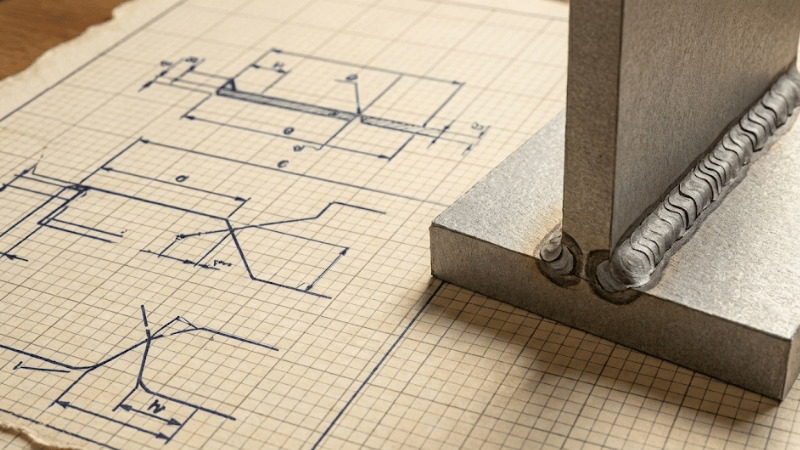
Ever stared at a blueprint and felt like you were trying to read alien hieroglyphics? A cryptic collection of flags, circles, and triangles that hold the entire project’s fate in their tiny lines. You’re not alone. Welding symbols are the universal, silent language of fabrication, and for the uninitiated, they can be a nightmare.
But what if you could read them fluently? What if you could glance at a complex drawing and know exactly what the engineer envisioned, down to the last millimeter? This guide will turn that confusion into confidence, transforming you from a symbol-guesser into a blueprint-master. Let’s decode the secrets.
Why These Little Drawings Are a Big Deal
Let’s be blunt: welding symbols aren’t just suggestions; they are legally binding instructions. They form a critical part of the contract between the client, the engineer, and the fabricator. They are the single source of truth that ensures a 100-ton bridge doesn’t unexpectedly disassemble itself under load.
Getting them right means a project is built to specification, passing inspection and ensuring safety. Getting them wrong can lead to catastrophic structural failures, wasted time, mountains of scrap metal, and legal liability.
In high-stakes industries like aerospace, pressure vessel manufacturing, and str
uctural steel, a misinterpreted symbol isn’t just a mistake—it’s a potential disaster. Knowing this language is non-negotiable for any serious welder, fabricator, or inspector.
The Anatomy of a Welding Symbol: Your Rosetta Stone
Every welding symbol, no matter how complex, is built on a standard framework. Once you learn the core components, you can methodically decipher any instruction.
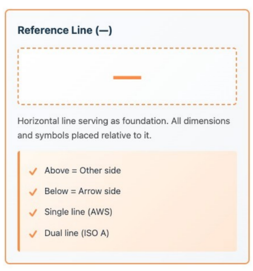
1. The Reference Line: Your Foundation
This horizontal line is the backbone of the entire symbol. All other instructions and symbols are attached to it. Think of it as the main sentence, with all the other parts being nouns, verbs, and adjectives that give it meaning.
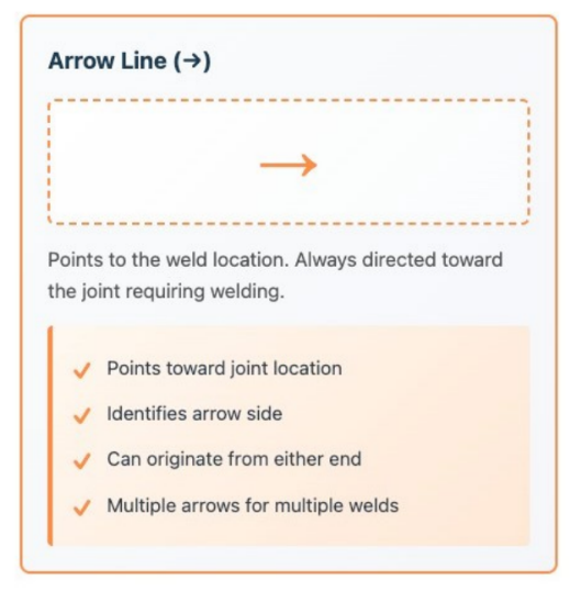
2. The Arrow: The “Where”
This simply points to the location, or joint, where the weld is to be performed. The arrow’s significance can be subtle; a break or “jog” in the arrow line is used for certain groove welds to indicate which piece of metal gets the special bevel preparation.
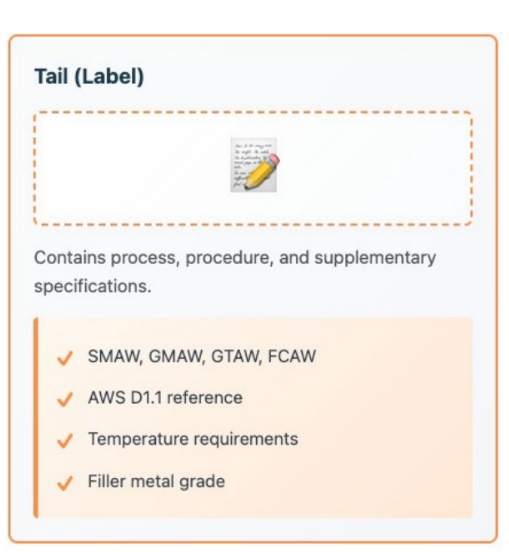
3. The Tail: The “How”
This forked end, which looks like a sideways “Y,” is only included when specific instructions are needed. The tail is where you’ll find information about the welding process (e.g., GMAW for MIG, GTAW for TIG), the type of electrode to be used, or any other notes not covered by the main symbol. If there are no special instructions, the tail is omitted.
The Core Concept: Decoding Location
This is the number one point of confusion, but the logic is simple. The reference line acts as a divider between two locations: the side of the joint the arrow is pointing to (arrow side) and the opposite side of the joint (other side).
- Symbol Below the Line: If the weld symbol (like a triangle for a fillet weld) is placed below the reference line, you perform the weld on the “arrow side” of the joint.
- Symbol Above the Line: If the weld symbol is placed above the reference line, you perform the weld on the “other side” of the joint.
- Symbol on Both Sides: If you see symbols on both the top and bottom, it means a weld is required on both sides of the joint.
Think of the reference line as a mirror or a dividing wall. The symbol’s position tells you which side of that wall to work on.
The Alphabet: Basic Weld Symbols Explained
While the official AWS A2.4 Standard for Welding Symbols contains dozens of symbols, a handful make up 90% of what you’ll encounter. These symbols define the physical shape of the weld and the preparation of the joint.
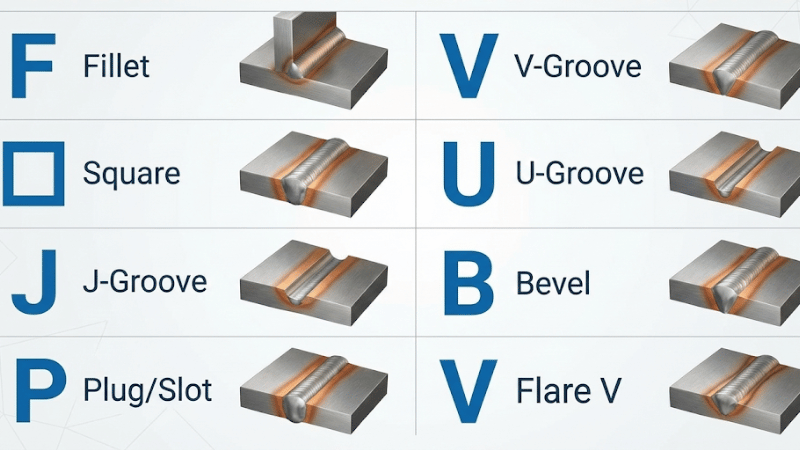
Fillet Welds (The Triangle)
This is the undisputed king of welding symbols. The right-angled triangle represents a fillet weld, used to join corner joints, T-joints, and lap joints.
- Numbers: A number to the left of the triangle specifies the leg size of the weld. Numbers to the right specify the length of the weld. If you see two numbers to the right separated by a hyphen (e.g., 3-5), it denotes an intermittent weld: 3-inch long welds spaced 5 inches apart from center to center.
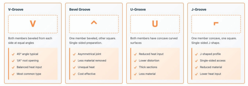
Groove Welds (The Heavy Hitters)
Groove welds are used to join pieces in the same plane (butt joints). The symbol indicates how the edges of the metal must be prepared before welding.
- Square Groove (Two Parallel Lines | |): Used for thin materials where the edges can be butted up together with a small gap (root opening) without any beveling.
- V-Groove (A “V” Shape): The most common groove weld. It indicates that the edges are beveled, forming a “V” shape to allow for deeper penetration on thicker plates. Numbers next to it can specify the angle of the bevel and the root opening.
- Bevel Groove (A “K” Shape on its Side): Similar to a V-groove, but only one side of the joint is beveled. The other side is left straight.
- U-Groove & J-Groove: Used for very thick metals. The U or J shape requires less weld metal to be deposited than a V-groove of the same depth, which saves time and reduces distortion. These require special machining.
Plug & Slot Welds (A Rectangle)
This symbol is used for joining overlapping plates by welding through a hole (plug) or a slot in the top piece. This is useful for adding strength and preventing warping over long spans. Numbers can indicate the diameter, depth of fill, and spacing of the plugs/slots.
The Grammar: Adding Detail with Supplementary Symbols
These extra symbols modify the basic instruction, adding critical details about the weld’s extent, location, and finish.
Weld All-Around (The Circle)
A small circle drawn at the junction of the reference line and the arrow is a powerful command: weld continuously around the entire joint. This is common for welding a pipe or tube to a plate, ensuring a complete seal.
Field Weld (The Flag)
A solid flag rising from the junction of the reference line and arrow means the weld must be performed on-site (“in the field”) rather than in the controlled environment of the fabrication shop. This has major logistical implications for equipment and personnel.
Melt-Thru (The Shaded Semicircle)
This symbol, placed on the opposite side of the weld symbol, indicates that the weld must achieve 100% penetration, showing a visible reinforcement (bead) on the backside of the joint. This is absolutely critical for pressure piping and other joints where full-strength bonding is required.
Contour & Finish Symbols (Flat, Convex, Concave Lines)
These symbols specify the final desired shape of the weld face. They appear above the main weld symbol.
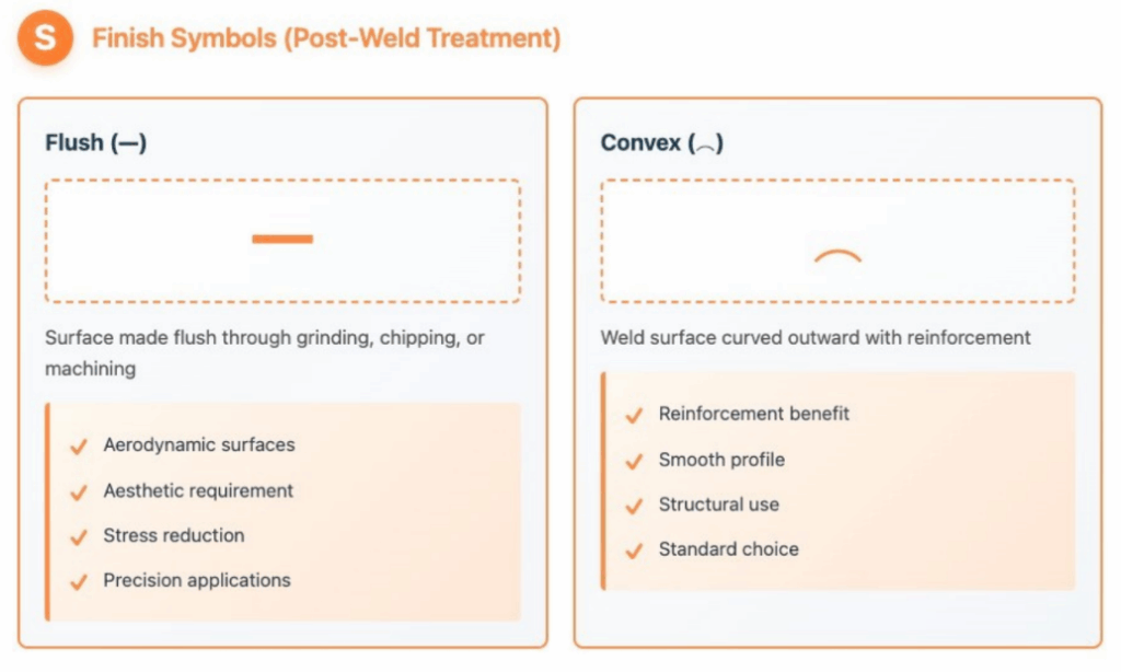
- Flat/Flush Contour (A Straight Line): The weld face must be finished flat with the base metal. This almost always requires post-weld grinding, chipping, or machining.
- Convex Contour (A Curved Line Bowing Out): The weld should have a slightly bulging, reinforced face. This is the natural shape of many welds and is often specified for maximum strength.
- Concave Contour (A Curved Line Bowing In): The weld should have a slightly indented face. This can be useful for reducing stress concentrations in certain applications.
From Confusion to Command
Welding symbols are the precise, powerful language of modern engineering and fabrication. They are not just drawings; they are commands that dictate the strength, safety, and ultimate quality of a finished product. By moving beyond guessing and committing to mastering this language, you elevate yourself from a technician to a true craftsperson.
By understanding the anatomy of the symbol and learning the alphabet of weld types and grammar of supplementary instructions, you are now equipped to read any blueprint with confidence. You hold the key to turning an engineer’s vision into a physical reality, correctly and safely.
Ensure Your Welds Meet the Blueprint.
Misinterpreting a single symbol can compromise an entire project, leading to costly rework and failed inspections. IKratz’s expert team is fluent in the language of welding, providing fabrication and consulting services that guarantee your final product matches the engineering design with perfect accuracy.
Contact us today to ensure your projects are built right, the first time.
Download ikratz’s free, high-resolution Welding Symbols Cheat Sheet to keep as a handy reference in your toolbox!
Frequently Asked Questions
- Q1: What’s the difference between the “arrow side” and the “other side”?
- A: The “arrow side” is the side of the joint that the arrow points to directly. The “other side” is the opposite side of that same joint. Symbols placed below the reference line apply to the arrow side; symbols placed above apply to the other side.
- Q2: What is the difference between a “weld symbol” and a “welding symbol”?
- A: A “weld symbol” is the character indicating the type of weld (e.g., the triangle for a fillet weld). The “welding symbol” is the entire assembly, including the reference line, arrow, tail, and all dimensions and supplementary information.
- Q3: What does the circle at the junction of the arrow and reference line mean?
- A: This is the “weld all around” symbol. It instructs the welder to perform the specified weld completely around the circumference or perimeter of the joint.
- Q4: What if a welding symbol has no tail?
- A: The tail is only used when a specific process, specification, or other reference is required. If there is no tail, it means no specific instruction is given, and the default or standard shop procedure should be used.

